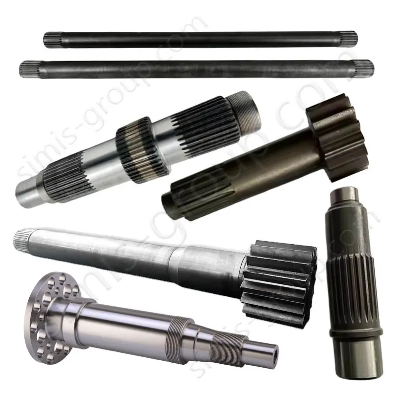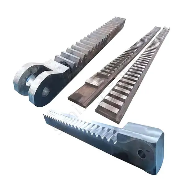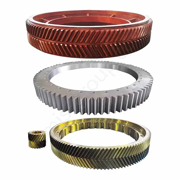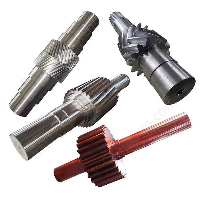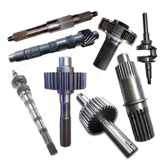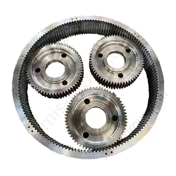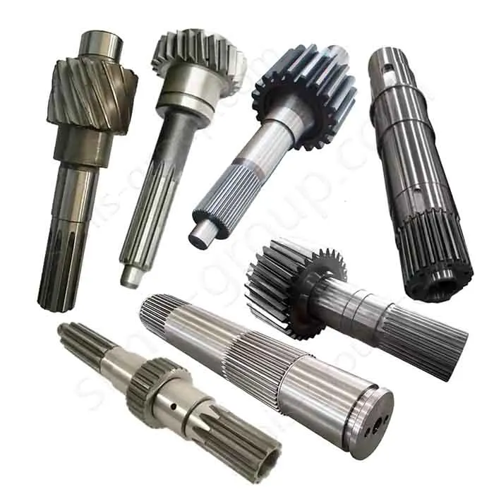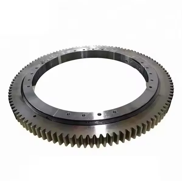
Custom Helical Gear Manufacturer
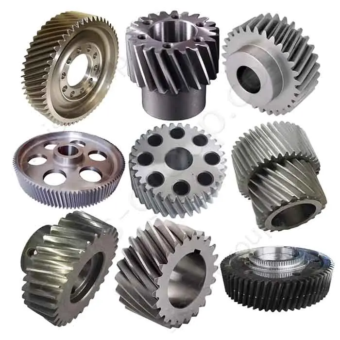


Helical Gear

Custom Helical Gear Manufacturing FAQs
Can SIMIS manufacture helical gears from our drawings or CAD models?
Yes. SIMIS accepts drawing-based OEM inquiries for custom helical gear components. We review the gear geometry, specified material, mating-gear information, expected torque and speed, required tooth accuracy, order volume and inspection needs before evaluating an appropriate blank and machining route. The final scope and manufacturing feasibility are confirmed against your approved technical documents.
Should a custom helical gear use a forged blank, a casting or machined bar stock?
The best starting form depends on gear diameter, section thickness, load cycles, material, quantity and tooling costs. A forged steel blank may be appropriate for demanding torque or fatigue conditions, while cast iron or cast steel can be considered for certain large, slower-running industrial gears if the design permits. Machining from bar stock can be practical for smaller batches or some geometries. Gear teeth normally require dedicated cutting or finishing operations regardless of the starting blank.
Which helical gear dimensions and tooth parameters must be specified?
Important inputs include normal module or diametral pitch, number of teeth, pressure angle, helix angle, left- or right-hand helix, face width and center distance with the mating gear. Drawings should also define bore and keyway or spline dimensions, datum surfaces, backlash targets, tooth modifications and the applicable accuracy or inspection standard. These details help prevent an apparently correct gear from having an unsuitable mesh.
Do all custom helical gears require gear grinding and high-precision inspection?
No. Hobbing or other tooth-cutting methods may be sufficient for some applications; finish grinding or honing is considered when the specified tooth accuracy, noise, load and processing route require it. Inspection scope should match the agreed drawing and gear accuracy grade. We would discuss profile, helix, pitch, runout and relevant material tests where they are required rather than assume that every gear needs the same operations.
What should we send to request an OEM helical gear quotation?
Send 2D drawings and, if available, 3D models, the mating gear specification, material grade, normal module, tooth count, pressure and helix angles, helix hand, face width, dimensions, target accuracy class and batch or annual quantity. Please also include required hardness or case depth, surface finish, inspection reports and any special application loads. If a detail is still under design review, identify it as provisional.
OEM Helical Gears Manufactured to Customer Specifications
Helical gears transfer torque through angled teeth that engage progressively as the gears rotate. In a correctly designed gear pair, this geometry can support smooth power transfer, but it also creates axial thrust that the shafts and bearings must accommodate. Reliable performance therefore depends not only on the gear blank and tooth form but also on the mating gear, alignment, lubrication and application loads.
SIMIS supports inquiries for custom metal helical gears for industrial machinery, reducers, drive systems, energy equipment and related OEM applications. Depending on the specification, the manufacturing route may combine a forged, cast or stock-machined gear blank with turning, tooth cutting, selective finishing and customer-specified material processing. Our focus is the customer's finished gear drawing, not a one-size-fits-all gear specification.
If you need related parts for a transmission assembly, see our custom gearbox housings and custom gear rotary shafts pages. These components may share critical datums and assembly requirements with the helical gear.

Choosing a Helical Gear Blank: Forging, Casting or Machining
The manufacturing route must address both the material structure of the blank and the final tooth geometry. Forming an approximate gear shape does not remove the need to verify tooth accuracy and fit. The following options are technical starting points for project review, not guaranteed selections for every part.
| Manufacturing route | Potential project fit | Engineering questions to resolve |
|---|---|---|
| Closed-die forging of steel blanks | Selected recurring-production gears requiring robust mechanical properties | Tooling economics, section geometry, material flow, planned machining stock and batch quantity |
| Open-die forging or ring rolling | Larger gear blanks or ring-shaped components when appropriate | Blank dimensions, material specification, internal soundness, turning allowances and handling |
| Cast iron or cast steel blank | Selected large or relatively low-speed gears where casting is allowed by the design | Defect acceptance, section thickness, intended contact load, damping needs and machining stock |
| Machining from bar or plate | Certain smaller batches, prototype quantities or designs requiring limited special tooling | Material availability, stock waste, geometry, machining time and distortion risks |
| CNC turning and gear cutting | Bores, faces, mounting features, hobbing and suitable finish operations | Profile, helix, pitch, runout, tooth finish and functional datum consistency |
For gear rings or a different tooth arrangement, related examples include our custom ring gears, custom spur gears and custom planetary gear components. Each requires its own design and inspection requirements; the same process choice cannot simply be copied between products.

Helical Gear Geometry: Parameters That Affect Fit and Performance
Gear geometry often determines whether an otherwise good-looking part can work correctly with an existing reducer or drive. Before producing tooling or cutting teeth, the manufacturer and buyer should align on the reference system, mating gear and accuracy expectations.
Normal module and tooth count: these define tooth size and help establish the gear's reference geometry. If the drawing uses diametral pitch, the specification must state the appropriate system and units.
Helix angle and helix hand: the required angle and left- or right-hand orientation must match the mating gear and shaft layout. Helical gears generate axial forces that affect bearings and housing design.
Pressure angle and tooth modifications: the tooth form, tip relief, profile correction and crowning requirements may affect contact behavior, noise and durability.
Face width and center distance: the load-bearing contact and mating alignment must be evaluated together with the gearbox installation.
Datum, bore and shaft features: the bore, keyway, spline, shoulder and locating faces must be controlled relative to the gear tooth geometry.
Backlash and inspection class: the engineering specification should identify allowable backlash and the applicable measurement and tolerance references.
For example, a helical gear intended for a high-speed reducer may place more emphasis on tooth flank accuracy and noise than a slow, heavily loaded industrial gear. These are design-specific requirements. They should be stated on the drawing rather than inferred from a generic promise of “high precision.”

Material Choices for Custom Helical Gears
Material choice needs to balance contact fatigue, tooth-root bending strength, shock loading, wear, machinability and production cost. The grades below are representative engineering options, not a statement that every grade is available for every size or operation.
| Material option | Why it may be selected | Key project considerations |
|---|---|---|
| Case-hardening alloy steel, such as AISI 8620 or a specified equivalent | Gears requiring a wear-resistant tooth surface and a tougher core | Approved case-hardening route, effective case depth, distortion allowance and hardness verification |
| Quenched-and-tempered alloy steel, such as AISI 4140/42CrMo | Industrial gears needing useful strength and toughness | Section size, achievable hardness, tooth finishing and applied load spectrum |
| Medium-carbon steel, such as AISI 1045 | Certain moderate-duty industrial gears or prototypes | Wear requirement, possible surface hardening, part size and acceptance specification |
| Ductile or gray cast iron | Selected large, slower-speed gears where the engineering design permits | Local strength, damping, fatigue demands, casting quality and application restrictions |
| Stainless steel or other specified alloys | Selected corrosive or special-service operating conditions | Required strength, galling/wear behavior, cost and mating materials |
The final material grade and any heat-treatment condition must be specified or approved by the buyer. Case hardness or case depth should never be quoted as a universal value for all custom helical gears; it depends on the chosen material and service requirements.

Gear Cutting, Finish Machining and Tooth Accuracy
Turning and datum preparation
Machining typically begins by establishing the bore, faces or other functional locating features. Consistent datums matter because tooth profile accuracy alone cannot correct excessive bore-to-tooth runout or incompatible shaft features.
Tooth cutting and finishing
Hobbing is widely used for cylindrical helical teeth when suitable for the part. Milling, shaping or other approaches may be considered for special geometry, and grinding or honing may be added when the specified accuracy and process sequence justify them. Finish processes should be agreed with the customer, not assumed for every order.
Tooth inspection and dimensional verification
A practical inspection plan can address involute profile deviation, helix/lead deviation, tooth pitch, runout, tooth thickness and the critical bore or shaft interfaces. When an accuracy classification is specified, the agreed standard and edition should appear on the drawing. ISO 1328-1, for example, provides a system for classifying deviations of cylindrical gear tooth flanks; it does not by itself certify how a finished transmission will perform.
For a high-speed gear, specified noise, contact pattern or assembly tests may be as important as isolated dimensional inspection. Ask for the test records actually required for your application, and agree on the measurement method and acceptance criteria in advance.

Helical Gear Applications and Manufacturing Priorities
A helical gear in a speed reducer faces different demands from one in an automotive gearbox or a heavily loaded mill drive. These application differences affect blank choice, tooth accuracy and inspection scope.
| Application | Common engineering concern | Manufacturing and RFQ focus |
|---|---|---|
| Industrial reducers and machinery | Continuous torque, alignment, wear and vibration | Tooth geometry, shaft fit, material condition and quantity |
| Vehicle-related transmissions | Variable load cycles, speed, noise and package limits | Fatigue performance, tooth finish, matched gear set and approval requirements |
| Mining and heavy machinery | High torque, contamination, shock and repairability | Robust blank selection, suitable hardness, inspection scope and interchangeability |
| Energy and power equipment | Long service intervals, cyclic loading and reliability | Material traceability, gear accuracy and application-specific testing |
| Agricultural machinery | Dirt exposure, variable loading and production cost | Replaceability, tolerance control, material choice and batch economics |
You can review other potential applications in our industrial machinery components category. Final gear design and service ratings remain the responsibility of the OEM or designated design authority.

How SIMIS Approaches a Drawing-Based Helical Gear Project
A meaningful quote needs enough detail to distinguish an economical blank from an overspecified or impractical production route. Our goal is to review the drawings and align the proposed process with the intended gear application.
1. Send the gear definition: 2D drawing, 3D model if available, mating-gear parameters, tooth geometry, material and order quantity.
2. Review the blank and process: evaluate forging, casting or stock machining, and identify any critical features or unavailable specifications.
3. Confirm gear-cutting and finishing needs: define tooth accuracy, surface finish, material condition and inspection standards based on the application.
4. Discuss sampling and documentation: agree on whether prototypes, first-article inspections, material records or dimensional reports are required.
5. Finalize the RFQ: clarify tooling if applicable, sample and batch quantities, delivery assumptions and the approved drawing revision.
If your helical gear must fit an existing reducer, please provide the mating-gear drawing and reference assembly information as well. Supplying only the outside diameter and number of teeth may not be enough to determine compatibility.
Request a custom helical gear quotation: contact the SIMIS team or send your engineering drawings to info@simis-group.com. We can review manufacturing feasibility and discuss a quote for your specific part.