Custom Crank & Crank Arm Manufacturer


Crank & Crank Arm

Custom Crank & Crank Arm Manufacturing FAQs
Can SIMIS manufacture crank arms to our 2D drawings or 3D CAD models?
Yes. SIMIS supplies OEM metal cranks and crank arms according to customer drawings rather than a fixed catalog dimension. We review the lever length, connection profiles, material, working load, finishing requirements and annual quantity before proposing forging, casting or machining. A crank arm may be supplied as a machined metal component or according to a more detailed project specification.
Should a crank arm be forged, cast or machined from billet?
The choice depends on cyclic bending and torque, weight targets, required features and production volume. Closed-die forging can suit repeated production of loaded steel or aluminum arms. Casting may suit complex contours and selected load cases when design validation supports it. Machining from billet is often worth evaluating for prototypes or small series because it avoids dedicated forming dies.
Which dimensions matter most for bicycle crank arms and industrial cranks?
For bicycle designs, the spindle connection, pedal thread, arm length measured between functional axes, left/right orientation and available frame clearance are critical. For industrial cranks, the pivot bore, drive interface, eccentric offset, arm thickness and pin or rod connection must be checked against the assembly drawing. Datum-based tolerances should reflect the intended fit and motion.
Can you provide heat treatment, surface finishing and inspection?
These steps can be planned as part of the OEM process route. Inspection may include material verification, important dimensions, hole or thread gauges, surface condition and specified hardness; fatigue, proof-load or non-destructive tests are agreed separately when applicable. No universal fatigue-life or certification claim can replace the requirements of the actual design.
What is needed for a custom crank arm quotation?
Please send a 2D drawing and, if possible, a STEP/IGES model, with material grade or preferred alternatives, annual demand, trial quantity, mating shaft or spindle details, connection thread specifications, surface finish, loading conditions and inspection documents required. SIMIS can then review the manufacturability and quotation scope.
OEM Custom Metal Cranks and Crank Arms
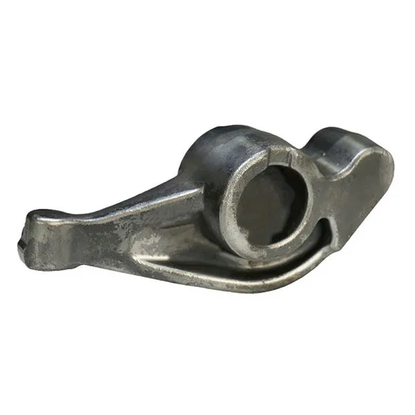
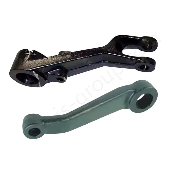
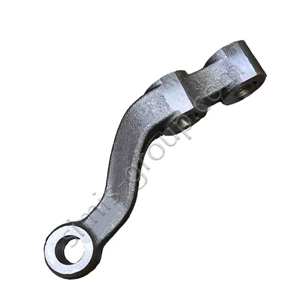
SIMIS manufactures custom crank arms, offset levers and related motion-transfer parts for equipment builders. A crank arm is a lever that turns around a shaft or pivot and transfers force through another connection point. This includes bicycle crank arms, manual or powered mechanism cranks, and selected pump, actuator or linkage applications. The actual load path and interfaces vary substantially across these product families.
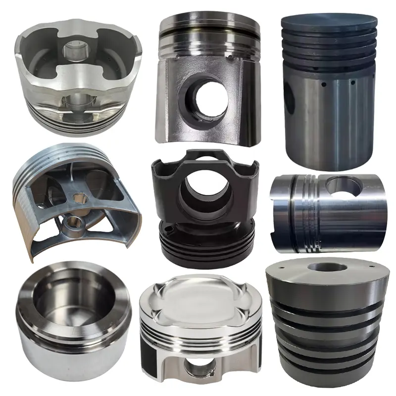
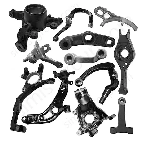
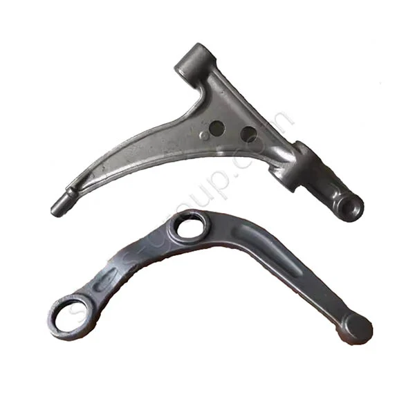
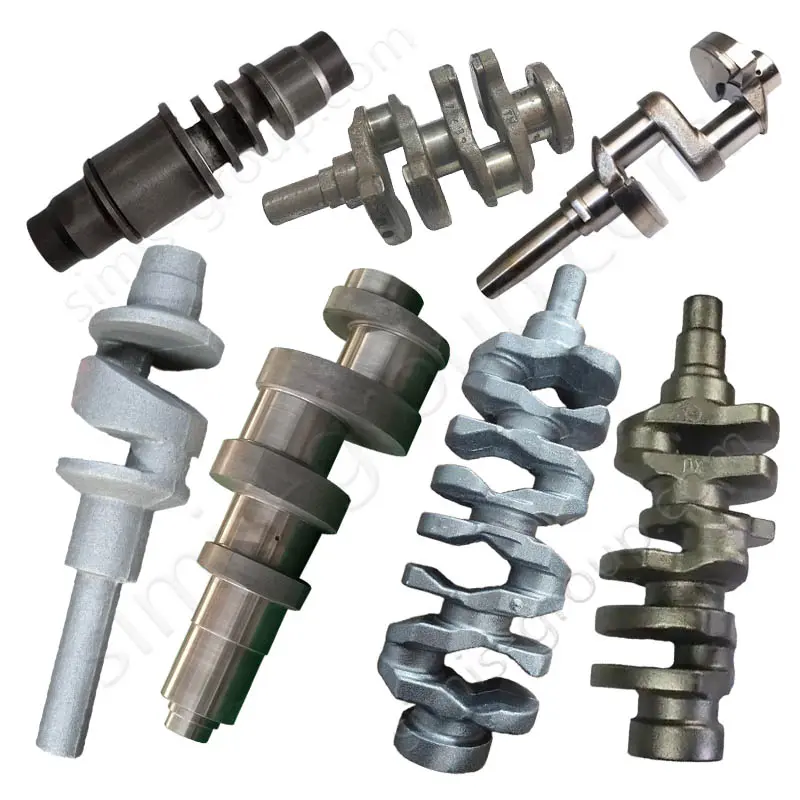
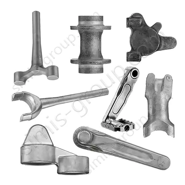
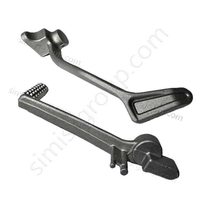
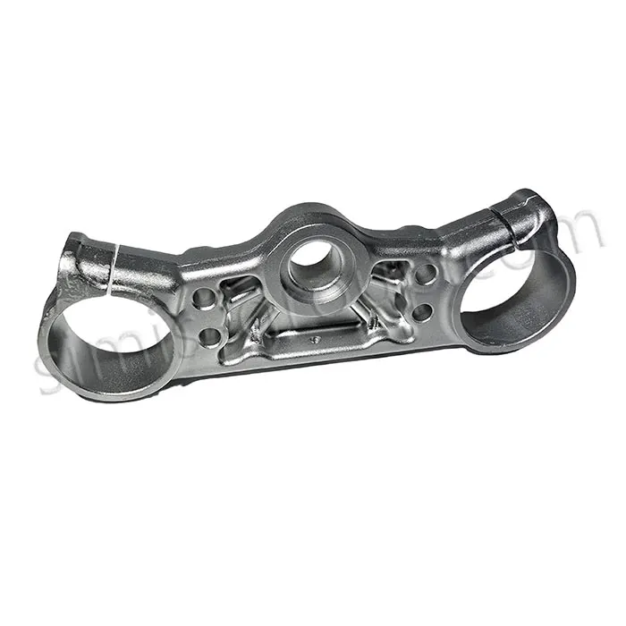
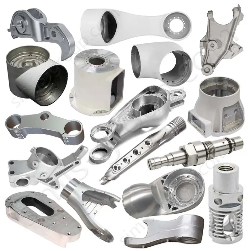
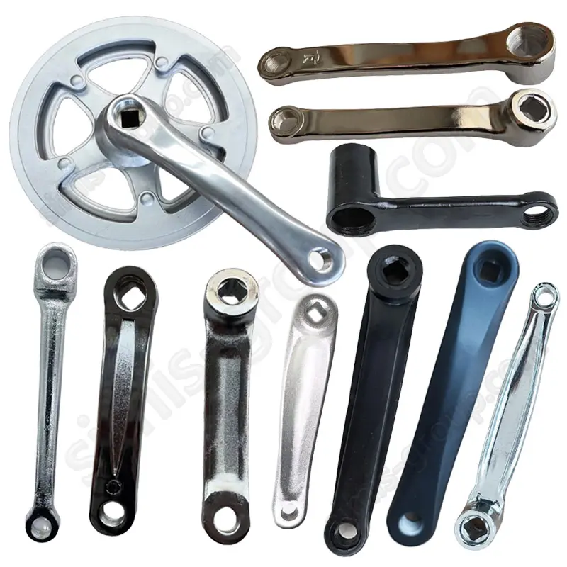
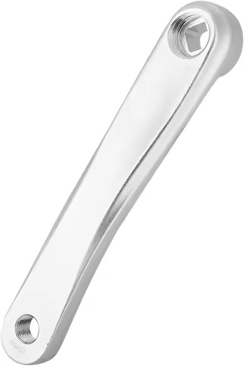
The photographs on this page primarily illustrate bicycle-style crank arms and similar metal lever profiles. If you are sourcing a multi-journal engine component, the separate custom crankshaft manufacturing page addresses a different geometry and production problem. This page focuses on individual arms and simpler crank or lever components produced to OEM drawings.

How to Choose the Manufacturing Process for a Crank Arm
A crank combines concentrated connection loads with a relatively long lever section. The process route must produce a sound transition from the hub or eye to the arm, leave enough stock for mating features and fit the ordered quantity. SIMIS can review closed-die forging for repeat-production arms, aluminum forging for selected lightweight parts and investment casting where the design and loading conditions justify a cast solution.
| Manufacturing route | Where it may fit | Points to confirm |
|---|---|---|
| Steel or aluminum closed-die forging | Medium/high-volume crank arms with significant bending, torque or impact duties | Draft, parting line, fillet transitions, die cost and post-forging machining allowance |
| Sand casting / investment casting | Selected complex crank or lever shapes and suitable duty classes | Wall thickness, local stress concentrations, casting quality requirements and fatigue validation |
| CNC machining from bar or plate | Prototype, low-volume or geometry requiring frequent revisions | Material removal, direction of stock properties, cycle time and achievable cost |
| Formed component plus finishing operations | Where a simple preform can be made economically | Access for bores, slots and thread machining; distortion and inspection planning |
For cast components, the final choice between sand casting and a more detailed mold route is driven by wall section, geometry, size, volume and performance specifications. Manufacturing process names alone do not establish a permissible load rating.

Material Selection: Steel, Aluminum Alloy and Ductile Iron
Material selection begins with how the arm will be loaded, not only with its weight. Alternating pedal loads, shock from an industrial mechanism, environmental exposure and the required joint strength can call for different material and treatment combinations.
| Material family | Potential advantages | Engineering considerations |
|---|---|---|
| Forged carbon or alloy steel | Useful for strong, tough load-bearing crank and lever designs | Weight, weldability where relevant, heat treatment, corrosion protection and fatigue validation |
| Forged aluminum alloy | Low density and good specific-strength potential for lightweight crank arms | Alloy/temper selection, section design, surface protection and thread-interface durability |
| Cast ductile iron | Castability and stiffness for suitably engineered machinery lever forms | Impact and fatigue duty, casting quality, local fillets, wall thickness and project verification |
| Other cast or machined alloys | May fit specialized corrosion, geometry or volume requirements | Check mechanical properties, thread retention, fabrication route and total cost |
A specific grade such as 42CrMo4 or 6061 should only be selected when it suits the specified design and available processing route; the drawing, material standard and heat-treatment condition should govern the order. Neither forging nor casting automatically guarantees a particular fatigue life.

Critical Dimensions and Interfaces on Custom Crank Arms
The most important dimensions are the ones that control assembly, movement and local stress. SIMIS reviews datum references and feature relationships during CNC machining planning so that the finished arm can mate with the customer’s shaft, pin, pedal or bearing system.
Crank length and functional center distance
For a bicycle-style arm, the center distance between the bottom-bracket spindle axis and pedal axis defines nominal crank length. For an industrial eccentric or crank lever, the comparable dimensions are the drive-pivot and output-pin centers. Location tolerance matters because it changes the motion path and mechanical leverage.
Spindle and drive connections
Connection designs may use square tapers, splines, keyed bores, clamping features, threaded hubs or other OEM-specific profiles. The drawing should identify the mating part and controlling standards or dimensions. An apparently similar hub shape is not necessarily interchangeable between assemblies.
Pedal threads, handedness and contact surfaces
Where a crank arm carries a bicycle pedal, thread size, pitch, thread depth and left/right handedness must be specified. Left- and right-side pedal threads can have opposite hands, and incorrect machining would prevent safe assembly. Thread-axis orientation, seating faces and gauges should be defined by the original equipment specification.
Arm clearance, offset and corner radii
Arm profile and offset determine clearance to the frame, chainstay or nearby mechanism. Smooth hub-to-arm transitions, sufficient section at the eye and controlled edge conditions deserve particular attention under cyclic bending. Crankset Q-factor and chainline are assembly-level dimensions; an isolated arm needs the corresponding mating geometry to confirm them.
Forging, Heat Treatment and Surface Finishing
Following forming or rough machining, the process route may include conditioning, solution treatment or aging for selected aluminum alloys, or quenching and tempering for suitable steels. The appropriate heat treatment is chosen for the supplied grade and desired properties, not applied identically to every crank arm.
Finish selection also depends on service conditions. Anodizing may be relevant to suitable aluminum crank arms; plating, paint or powder coating may protect steel components. Surface preparation and surface treatment must take account of dimensional buildup and whether threads, mating tapers or bearing interfaces need masking. Decorative polishing cannot substitute for a structural inspection.
For fatigue-sensitive geometry, the engineering review may cover machining marks, edge breaks, abrupt thickness changes, tooling marks and post-treatment distortion. Any fatigue or proof-load qualification must be separately specified and documented.
Applications: Bicycle Cranks and Industrial Motion Linkages
Bicycle and pedal-driven systems
Common features include pedal attachment holes, spindle interfaces, crank length and space for chainrings or associated assemblies. SIMIS can consider these as part of a drawing-based custom bicycle parts program, including batch inspection expectations and consistent left/right identification where requested.
Industrial hand cranks, pump levers and mechanisms
Other crank designs convert rotary input to oscillating or reciprocating movement in handling mechanisms, pumps, actuators and equipment linkages. For these parts, pivot-bore alignment, lever offset, clearance and the fastener or pin interface may be more important than bicycle-specific dimensions. Related custom link arms can use similar materials yet require a different assessment of load and motion.
Not every crank needs dynamic balancing
Dynamic balance is a system-level requirement determined by operating speed and assembly geometry. A slow-moving hand crank, an individual bicycle arm and a complete high-speed rotating assembly do not share one universal balance specification. Where mass matching or assembly balancing is needed, it should be included in the quotation and inspection plan.
Quality Inspection for OEM Custom Crank Arms
Quality planning starts with drawing tolerances and the locations that actually locate the part in use. SIMIS can arrange inspection activities through its quality control workflow according to the accepted purchase specification, rather than claiming every crank receives identical tests.
Incoming material: material grade and certificates when specified, plus relevant heat-treatment records.
Key dimensions: crank center distance, bore or drive profile, interface position, machined faces, threaded holes and specified geometric tolerances.
Surface and fit: inspection of edges, burrs, coating condition and gauges for functional threads or splines where applicable.
Additional verification: hardness, non-destructive testing, sample fatigue tests or proof-load tests only as required by the approved inspection plan.
Documentation: dimensional reports, traceability, test results or first-article records to the degree agreed for the OEM project.
Product performance cannot be inferred from a single hardness result or an unsupported fatigue-strength percentage. Part acceptance must follow the agreed requirements, including any relevant regulatory or equipment-specific standards.
Design for Manufacturing: Reducing Rework and Tooling Risk
Early DFM review can identify changes that reduce cost without changing the customer’s intended assembly function. Engineers should review whether forgings have realistic draft and parting surfaces; castings have workable walls and local radii; and machined components have secure datum surfaces. For long thin arms, distortion during machining and heat treatment also needs consideration.
The choice between a dedicated die and billet machining should reflect projected annual quantity and design stability. When interfaces are still changing, prototype machining may help confirm fit before die investment. On approved repeat designs, forming routes can be assessed for material use and cycle time.
Why Source Drawing-Based Crank Arms from SIMIS?
SIMIS supports cross-process custom manufacturing for buyers needing forgings or castings followed by precision machining and selected finishing operations. The strongest sourcing result comes from a documented design review, realistic process selection, controlled critical features and inspection matched to the duty of the part.
For crank arms, this means giving special attention to the hub transition, functional center distance, mating shaft features and threaded interfaces. These details generally influence successful assembly more directly than broad claims about universal ultra-precision or guaranteed vibration-free operation.

Request a Quote for Custom Crank & Crank Arm Manufacturing
Send your drawing package to info@simis-group.com or use the product inquiry form. Include 2D/3D drawings, material grade, annual volume, prototype quantity, mating-part details, finish and functional test or certification requirements. For bicycle crank arms, identify crank length, spindle interface, pedal-thread details, left/right variants and assembly clearance; for industrial cranks, specify pivot arrangement, load direction, torque and duty cycle.
SIMIS will review the possible casting, forging and machining route and discuss the information needed for a manufacturing quotation. All feature tolerances, mechanical properties, testing and inspection deliverables remain subject to the mutually approved technical specification.