Custom Engine Cylinder Head Manufacturer
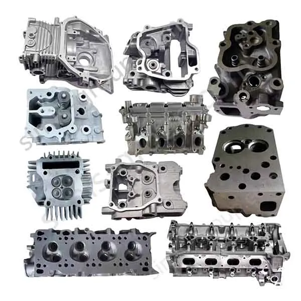


Engine Cylinder Head

Custom Engine Cylinder Head Manufacturing FAQs
Can SIMIS manufacture engine cylinder heads from our 2D or 3D drawings?
SIMIS accepts OEM inquiries for custom cylinder head castings and machined components based on customer-supplied drawings. We review the combustion-chamber layout, intake and exhaust passages, cooling jackets, selected alloy, machining datums and production quantity before proposing a manufacturing route. Feasibility and final specifications are confirmed for each project.
How do you choose between aluminum and cast iron for a cylinder head?
The choice depends on engine design, thermal loading, weight targets, mechanical requirements and the customer’s material specification. Aluminum castings can reduce weight and transfer heat effectively, while gray or ductile cast iron may be suitable for selected industrial and heavy-duty applications. Material grade, casting method and any heat treatment must be reviewed together.
How are water jackets and intake/exhaust ports formed in a cylinder head casting?
Complex internal passages typically require a carefully designed core system or another validated cavity-forming method. During design-for-manufacture review, attention is given to core location, wall thickness, core removal, casting allowances and access for subsequent machining and inspection. The feasible design depends on the chosen casting route.
Which dimensions and tests matter most for OEM cylinder heads?
Typical drawing-controlled features include the cylinder-head deck, valve seat and guide alignment, camshaft bearing locations, mounting holes and gasket interfaces. Depending on the project, acceptance may also include material verification, dimensional inspection, coolant-passage leak testing and agreed non-destructive examinations. No one test plan applies to every head design.
What information should we send for a custom cylinder head quotation?
Please share the 2D drawing and 3D CAD model, including internal water jackets and port geometry where available. Also specify material grade, annual volume, machining scope, critical tolerances, intended service environment and the applicable inspection or test standard. If the design is still being developed, identify which dimensions and interfaces are fixed.
OEM Engine Cylinder Heads Manufactured to Your Drawings
An engine cylinder head combines combustion sealing surfaces, valve-train features, intake and exhaust passages, coolant circuits and numerous precision interfaces in one component. For an OEM buyer, successful manufacture depends on coordinating the casting geometry with the locations that must be finish-machined and inspected—not simply selecting a casting process.
SIMIS supports drawing-based inquiries for aluminum alloy and cast iron cylinder heads, with manufacturing routes evaluated around part geometry, production volume and required finishing operations. Whether the project concerns a passenger-vehicle engine, industrial power unit or selected heavy-duty application, customer-approved technical specifications determine the actual scope.

Engineering Review: What Makes a Cylinder Head Difficult to Cast?
Internal water jackets and core stability
Cooling galleries often pass close to the combustion face, valve bridges and exhaust ports. Core design must account for supported and unsupported sections, core positioning, minimum walls, metal flow and the ability to remove core material. A casting-design review should consider realistic core-print locations, wall thickness transitions and inspection accessibility before tooling is approved.
Intake/exhaust passages and combustion-chamber features
Port geometry is constrained by available casting space, the selected core process and any required CNC finishing. A complex port shape does not automatically mean better engine performance: airflow behavior and combustion results must be established through the engine developer’s analysis and testing. The manufacturing task is to produce the approved geometry consistently within the specified tolerance scheme.
Deck, valve bridge and thermal-stress areas
Sharp changes in section thickness and thermally loaded areas can affect filling, feeding, residual stress and susceptibility to cracking. Fillets, material transitions, machining stock and local soundness criteria should therefore be discussed during DFM. Process simulation or trial castings may be appropriate where risk and program volume justify them.
Choosing a Cylinder Head Casting Process
A cylinder head may be produced by several casting routes, but the correct method depends on actual geometry, alloy, tooling economics and inspection requirements. The following is a project-selection guide rather than a claim that every process is appropriate for every head.
| Manufacturing route | Potential application | Important DFM considerations |
|---|---|---|
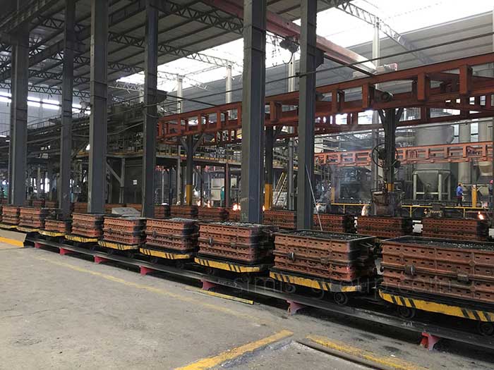
| Sand casting | Cast iron or aluminum heads with complex cavities, prototypes or varying production volumes. | Core construction, dimensional allowance, gating/feeding and cleaning access. |
| Shell mold casting | Selected iron cylinder-head designs where the process offers useful dimensional and surface-control benefits. | Core package compatibility, tooling and the actual part-size limits. |
| Gravity permanent mold casting | Selected aluminum heads where production volume justifies permanent tooling. | Feasibility of sand cores, die thermal control, solidification and mold access. |
| Lost foam casting | Certain complex geometries, subject to verified process capability and internal-passage quality requirements. | Pattern design, coating, gas management and validation of critical internal features. |
| CNC machining | Deck faces, guide and seat features, bores, mounting interfaces and other drawing-controlled surfaces. | Datums, fixturing, machining sequence and inspection access. |
SIMIS can review potential combinations of casting, machining and any specified treatment. For example, an iron casting may require a different core and finishing strategy than an aluminum permanent-mold part. Final process selection should follow the approved drawing and manufacturing-feasibility assessment.

Material Selection: Aluminum Alloy vs. Cast Iron
| Material family | Why an OEM may consider it | What to verify |
|---|---|---|
| Cast aluminum alloys | Weight reduction and good thermal conductivity for many engine-head applications. | Exact casting grade, heat-treatment condition, porosity acceptance, thermal cycling and threaded-insert strategy. |
| Gray cast iron | Rigidity, damping and established use in selected industrial or diesel-engine applications. | Customer-specified grade, local wall sections, machining requirements and thermal-fatigue considerations. |
| Ductile cast iron | Higher ductility and strength than typical gray iron for selected designs. | Grade suitability, casting soundness, operating temperature and design approval. |
Material families should not be treated as interchangeable. Valve-seat inserts, valve-guide materials, gasket systems, fastener loads and coolant chemistry also affect the complete engine-head specification. Any specific alloy, standard and mechanical-property target must be confirmed with the customer before production.
Precision Machining of Cylinder Head Interfaces
Casting creates the basic geometry; critical assembly features generally require machining. This work must be planned using datums that preserve the functional relationship among the cylinder-head deck, valve gear and the mating engine cylinder block.
Head-to-block deck: flatness, surface finish and bolt-pattern location must follow the gasket and engine designer’s requirements.
Valve guides and valve seats: bore position, seat-to-guide concentricity and any insert installation procedure should be controlled by the drawing.
Camshaft bearing locations: supported engines may require alignment checks, line boring or other geometry-dependent operations.
Intake/exhaust flanges: sealing-face flatness, port alignment and bolt-hole position affect fit with the intake and exhaust manifold.
Coolant and oil interfaces: threaded ports, plugs, passages and gasket surfaces must be accessible to machining, cleaning and verification.
Tolerances should be assigned to each critical feature rather than advertised as a single blanket “micron-level” figure. During quoting, the required machining scope and inspection method should be specified, particularly where a head is supplied as a raw casting rather than a fully machined component.
Inspection and Acceptance Planning for Cylinder Heads
Because casting discontinuities, geometry errors and leakage risks can affect a cylinder head differently, the acceptance plan should distinguish material, dimensions and internal integrity. The relevant requirements must come from the engineering drawings and agreed acceptance criteria.
| Inspection focus | Typical verification approach |
|---|---|
| Material identity and properties | Heat records, composition verification and appropriate mechanical-property tests when specified. |
| Deck and precision bores | Dimensional checks using appropriate gauges, CMM or other approved measuring equipment. |
| Core-formed passages | Visual or borescope access where feasible, cleanliness checks and customer-defined internal geometry assessment. |
| Coolant or oil circuit integrity | Leak or pressure testing according to the approved test medium, pressure, duration and acceptance limit. |
| Internal casting soundness | Radiographic, ultrasonic or other non-destructive examination only where the geometry and project specification call for it. |
Inspection may involve different stages for the raw casting and final machined component. SIMIS discusses the needed acceptance scope with customers rather than presenting pressure testing, X-ray inspection or zero-leakage performance as unconditional guarantees for every cylinder head. Additional information on the broader approach is available on our quality control page.

Applications and Production Considerations
Cylinder-head projects vary substantially across small engines, vehicle powertrains, diesel equipment and industrial power-generation systems. The relevant engineering issue is not just the engine category, but the combination of combustion loading, cooling architecture, valve-train arrangement, material and annual demand.
Automotive and motorcycle engines: often prioritize packaging, weight, port geometry and precision valve-train interfaces.
Commercial and industrial engines: may emphasize service-life requirements, thermal cycling, maintainability and heavy-duty material selections.
Stationary power units: can involve specified duty cycles, coolant chemistry, gasket design and dimensional traceability.
Prototype and replacement programs: may place greater emphasis on tooling economics and a complete technical data package.
For closely related engine components, explore our custom engine cylinder block, intake/exhaust manifold and crankshaft pages. These components interact at the system level, although each has its own manufacturing and inspection requirements.
How SIMIS Approaches an OEM Cylinder Head RFQ
A reliable quotation starts by defining whether the inquiry is for a raw casting, a partially machined cylinder head or a more fully finished component. From there, the casting route, core system, tooling, machining setup and quality plan can be evaluated together.
1. Review drawings: obtain the latest 2D specifications, 3D model and any available internal-passage models.
2. Confirm requirements: establish material grade, application, yearly volume, machining state, dimensional datums and special characteristics.
3. Assess manufacturability: review process suitability, core access, machining allowance, tooling needs and likely design risks.
4. Define inspection: agree on the critical measurements, material records and any leak-testing or NDT requirements.
5. Prepare the quotation: confirm the proposed supply scope, tooling assumptions, estimated production schedule and commercial terms.
If your project involves a new or replacement engine cylinder head, send your drawing package and estimated demand to info@simis-group.com. SIMIS can review the technical requirements and discuss a suitable OEM manufacturing solution. You can also use the inquiry form on this page.