Custom Oil Filter Housing Manufacturer
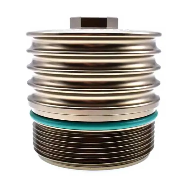


Oil Filter Housing

Custom Oil Filter Housing Manufacturing FAQs
1. Can SIMIS manufacture oil filter housings from our 2D or 3D drawings?
Yes. SIMIS supports drawing-based OEM metal oil filter housings, filter heads and selected oil-cooler module housings for engine and industrial-equipment manufacturers. We evaluate the part geometry, material specification, internal oil passages, sealing interfaces, expected quantity and required inspections before selecting a casting and machining route. The final manufacturing and testing scope is confirmed during quotation.
2. Which casting process is suitable for an aluminum oil filter housing?
High-pressure die casting can be considered for suitable aluminum housings with repeat production demand, while gravity permanent mold or sand casting may be appropriate for different shapes, volumes and internal passage designs. Core requirements, wall thickness, die access, sealing surfaces and the permitted porosity level influence the choice. No casting process alone guarantees a pressure-tight housing; sealing performance must be evaluated against the specified acceptance criteria.
3. Which dimensions are most important on a custom oil filter housing?
Typical critical features include the filter attachment thread or cartridge bore, gasket groove or face, mounting-hole pattern, oil inlet and outlet ports, sensor ports, bypass-valve seat and any oil-to-coolant interfaces. The drawing should identify functional datums, thread standards, flatness, surface finish, wall thickness and relevant geometric tolerances. Only features requiring the specified accuracy need to be finished by machining.
4. Can porosity and oil leakage be controlled in cast filter housings?
Casting design, alloy selection, process controls and inspection can be planned around the required leak performance. Where technically suitable and permitted by the OEM, impregnation may be evaluated for certain casting microporosity, but it does not repair structural cracks, replace sound casting design or automatically certify the part for pressure service. Test media, pressure, duration, leakage limit and whether testing covers a bare casting or assembled module should be defined before production.
5. What information is required to quote OEM oil filter housings?
Please provide 2D drawings and preferably a 3D CAD model, material or alloy grade, part weight or overall dimensions, anticipated order volume, port and thread specifications, sealing surface requirements, working oil pressure and temperature, oil/coolant compatibility, plus any inspection or documentation criteria. State whether you need a raw casting, a machined casting or a component with specified accessories; these are different quotation scopes.
Drawing-Based OEM Oil Filter Housing and Filter Head Castings
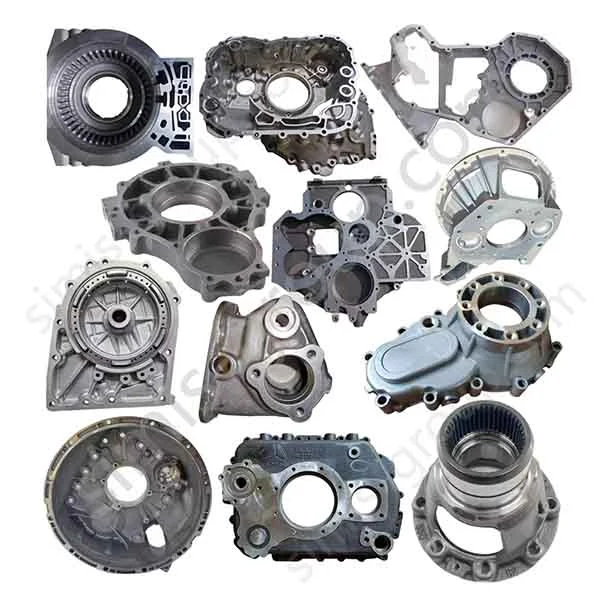
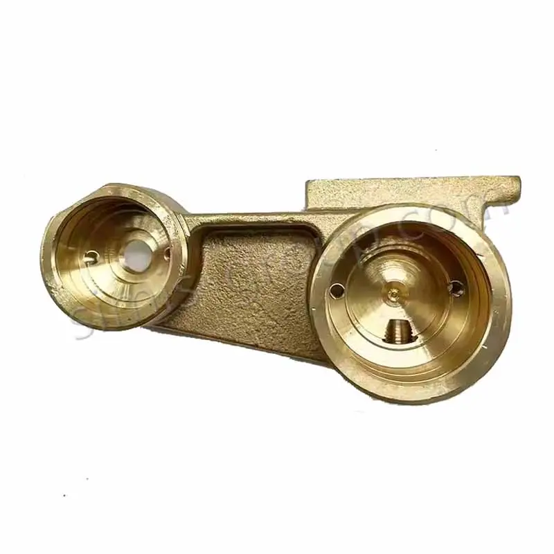
An oil filter housing supports the filter element or spin-on filter and routes lubricating oil through the filtration circuit. Depending on the customer’s equipment design, a housing may be a simple mounting head with inlet and outlet ports, a canister or cartridge-filter body, or a more complex casting integrating bypass passages, sensor bosses and an oil cooler interface. The housing’s function depends on precise geometry and compatible sealing components—not merely on its external appearance.
SIMIS manufactures custom metal housing components to the customer’s approved drawings. A project may involve an aluminum casting for automotive engines, an iron housing for a stationary machine or a specified stainless alloy for a special operating environment. We help evaluate an appropriate forming process, machining allowances and inspection scope while the OEM retains responsibility for the complete lubrication-system design and its functional validation.

Key Oil Filter Housing Features to Define Before Manufacturing
Oil filter housings contain several interfaces that must work together. For complex castings, the position of an internal passage relative to the external mounting face can be just as important as the overall housing dimensions. The following features deserve special attention during drawing review:
| Housing feature | Manufacturing concern | What the OEM drawing should specify |
|---|---|---|
| Oil inlet and outlet channels | Core placement, local wall thickness, port orientation and internal passage continuity. | Passage geometry, minimum wall thickness, port location and cleanliness criteria. |
| Filter attachment / cartridge pocket | Filter fit, insertion clearance and possible threaded or stepped bore features. | Thread standard or bore size, depth, datum, fit and relevant surface finish. |
| Gasket face and O-ring groove | Contact geometry affects sealing of the assembled filter module. | Groove dimensions, face flatness, roughness and seal interface tolerance. |
| Bypass valve seat and auxiliary bores | Valve location and bore finish affect component fit, where the design includes a valve. | Bore diameter, seat geometry, position, finishing and applicable test requirements. |
| Mounting flange and bolt pattern | Alignment with engine block or machinery interface. | Hole spacing, true position, mounting-plane datum and fastener specification. |
| Oil cooler or coolant passages (if present) | Separate oil and coolant circuits and define the interfaces where two media are handled. | Channel boundaries, joint surfaces, materials, temperature and leak-test requirements. |
Not every housing contains a bypass valve, anti-drainback element or oil cooler. These features should appear in the article and quotation only when present in the actual customer design. For adjacent engine castings, our custom engine cylinder block page covers another class of oil and coolant passage component.
Casting Processes for Custom Oil Filter Housing Components
Aluminum High-Pressure Die Casting for Suitable Production Volumes
Aluminum pressure die casting is often evaluated for compact, repeat-production housings requiring mounting bosses, ribs and complex external contours. Tooling design must consider wall transitions, gate and vent locations, machining stock and any internal passages. Entrapped gas or shrinkage porosity can affect sealing performance, so porosity acceptance and the planned leak-check approach must be considered from the outset rather than assuming the die casting is automatically leak-free.
Sand and Shell Mold Casting for Iron, Steel and Complex Housings
Sand casting offers flexibility for gray iron, ductile iron and selected steel housing designs, including larger or lower-volume components that require sand cores. Shell mold casting may suit some smaller, repeatable shapes, depending on the alloy and geometry. Internal oil-channel design should be reviewed for core support, casting cleaning access and adequate machining allowances. These decisions influence not just cost, but also the feasibility of inspecting and cleaning each passage.
Investment Casting and Other Routes for Selected Designs
Investment casting can be evaluated for selected stainless-steel or other intricate metal components where the size, geometry, material and internal cavities suit the method. For certain aluminum designs, a gravity permanent-mold route may also be reviewed. None of these methods should be called the best option without the actual part drawing and production requirements.
CNC Machining of Seal Faces, Threads and Functional Bores
Following casting, CNC turning, milling, boring and tapping may be applied to functional surfaces: filter-mount threads, cartridge seats, gasket lands, port threads, locating bores and bolt holes. A consistent datum strategy is particularly important when the filter interface must align with a mounting face or the oil passage geometry. Where a design needs a specified flatness, geometric tolerance or surface roughness, that requirement should be identified on the drawing and checked by an agreed method.

Materials for Oil Filter Housings and Oil Cooler Module Castings
Material selection depends on working pressure, temperature cycling, installation load, lubricant compatibility, possible coolant contact, weight targets, casting geometry and projected volume. The material names below are potential engineering options, not a claim that every grade is available or approved for every housing.
| Material option | Why an OEM may consider it | Points to confirm |
|---|---|---|
| Cast aluminum alloys | Light weight, useful heat conductivity and suitability for several high-volume casting routes. | Exact casting grade, temperature conditions, machining needs, oil/coolant compatibility and acceptable porosity. |
| Gray cast iron | A practical casting option for some stationary machinery and heavy metal housings. | Pressure boundary design, local strength, wall thickness and the specified cast-iron grade. |
| Ductile iron | May suit certain housings requiring a different strength and toughness balance than gray iron. | Specified grade, pressure and mounting loads, section requirements and casting feasibility. |
| Cast stainless steel | An option for selected corrosive environments or special industrial designs. | Exact alloy grade, fluid chemistry, casting route and required inspection scope. |
| Specified cast or fabricated steel | Possible for particular industrial housings when approved by the designer. | Part design, manufacturability, material specification and joining or machining plan. |
The material alone cannot establish an allowable operating pressure or fatigue life. Oil chemistry, additives, coolant exposure and thermal cycles should all be part of the customer specification. For related precision housings used in machinery drives, see custom gearbox housing manufacturing.
Machining, Cleanliness and Leak-Test Planning
An oil filter housing may have multiple small passages and sealing interfaces. An appropriate inspection plan needs to reflect the risk associated with the actual drawing rather than relying on blanket claims of zero pores, perfect sealing or mandatory certification for every part.
Material and casting checks: verify the required alloy grade and inspect relevant casting surfaces; any radiography or other non-destructive examination should follow the agreed specification.
Dimensional checks: confirm mounting-face flatness, O-ring groove geometry, filter threads, port locations, valve bores and other critical-to-fit features.
Oil passage cleanliness: establish an agreed cleaning and inspection method for sand, chips, burrs or other residual material in accessible channels.
Leak or pressure testing: where specified, agree on test method, test medium, pressure, time, temperature condition, sample frequency and maximum permitted leakage.
Impregnation, if considered: require buyer approval and verify that any process used is suitable for the material, porosity condition and service requirements.
Documents: agree on inspection reports, material identification, traceability and any sample-approval records required by the OEM.
Important distinction: A satisfactory housing casting or leak-test report does not by itself validate filtration efficiency, bypass-valve calibration, oil cooler performance or durability of the complete assembled module. Such performance depends on the whole filter system and must be verified by the responsible equipment manufacturer.
Applications for Custom Oil Filter Housings
Oil filter housing designs differ substantially between compact engines and heavy industrial units. The drawing, material and pressure boundary should therefore be reviewed for the actual application rather than assuming one standard housing is suitable for all equipment.
Automotive and commercial vehicles: filter mounting heads and combined oil-filter/oil-cooler castings with defined engine mounting interfaces.
Diesel generators and stationary engines: larger filter brackets or housings requiring robust connections and serviceable element access.
Industrial compressors and machinery: custom oil-flow manifolds or filter housings with specified inlet/outlet connections and maintenance clearances.
Marine-related equipment: special metal housings whose material and sealing design must be compatible with the installation environment and maintenance requirements.
You can also explore other automotive and truck OEM metal parts or industrial machinery components produced according to customers’ drawings.

Request a Quote for Custom Oil Filter Housing Manufacturing
SIMIS focuses on the manufacture of OEM metal parts, not the retail sale of standard filter cartridges. For a reliable quotation, the most useful information is a fully dimensioned drawing showing the casting geometry, the surfaces to be machined and the functional interfaces to be inspected.
Design files: 2D drawings, 3D model and any existing casting or machining drawings.
Component definition: filter head, cartridge housing, oil cooler module housing or another specific metal part.
Materials and production: required alloy or approved alternatives, annual volume, prototype quantity and tooling expectations.
Oil and coolant circuits: flow passage design, working pressure and temperature, fluid types and any leak-test limits.
Interfaces and tolerances: threads, mounting bolt pattern, gasket lands, valve bores, critical datum scheme and roughness requirements.
Acceptance package: required material documents, dimensional inspection, casting examination, cleanliness criteria and other agreed test records.
For a drawing-based manufacturing review, contact SIMIS or email info@simis-group.com. Please attach your oil filter housing drawings and target quantities so that a suitable casting, machining and inspection plan can be evaluated.