Custom Shock Mount Bracket Manufacturer
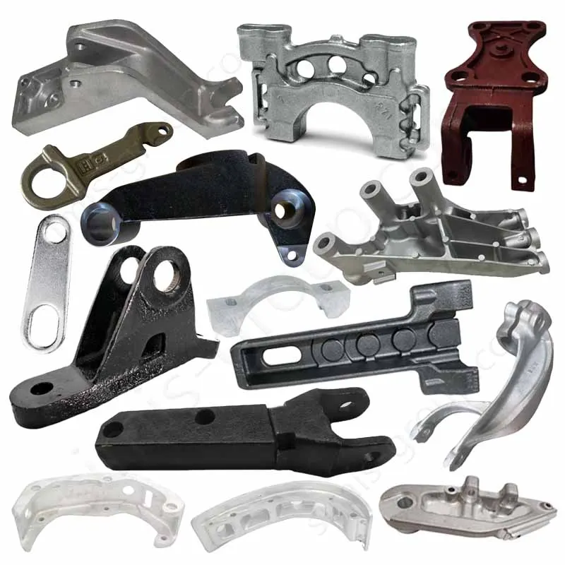
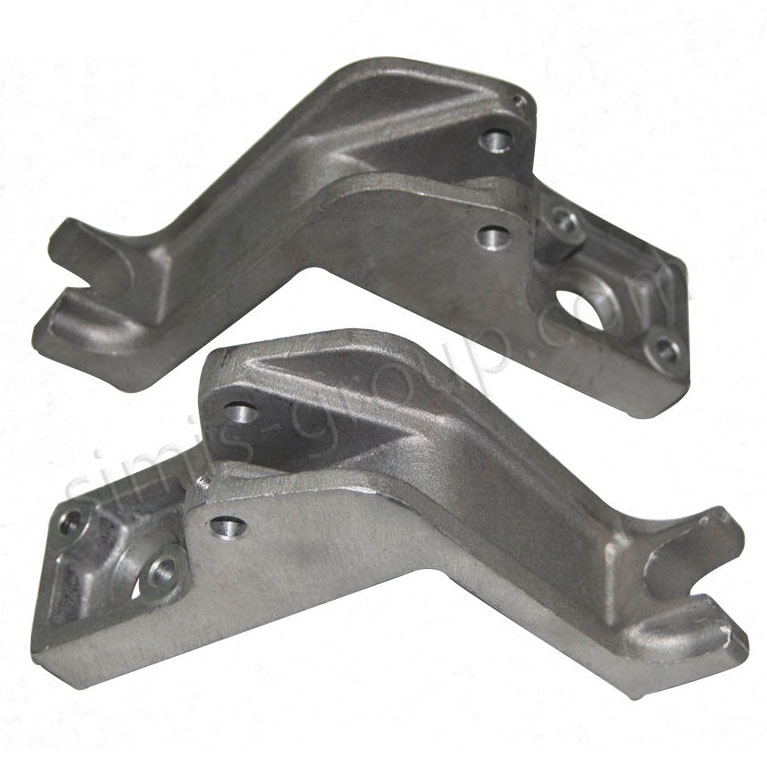
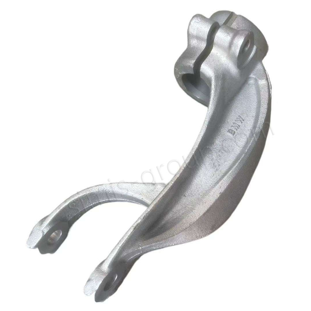
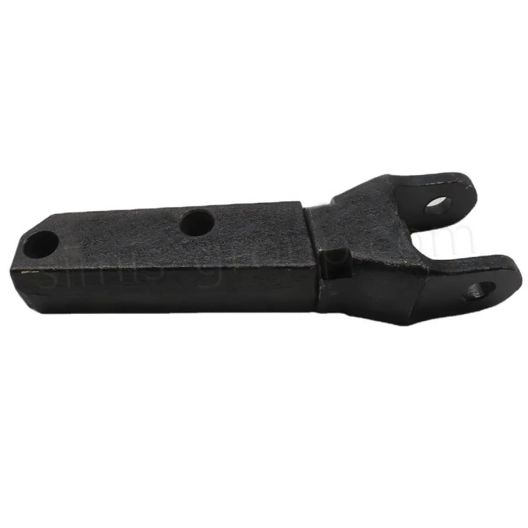
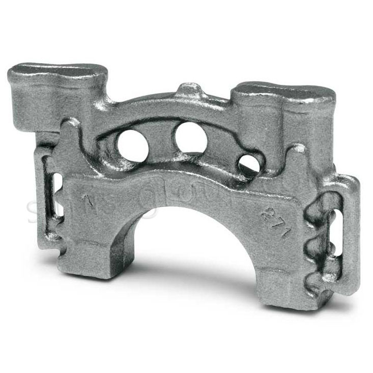
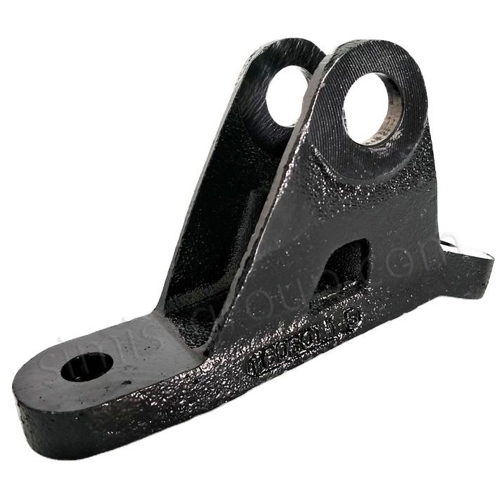

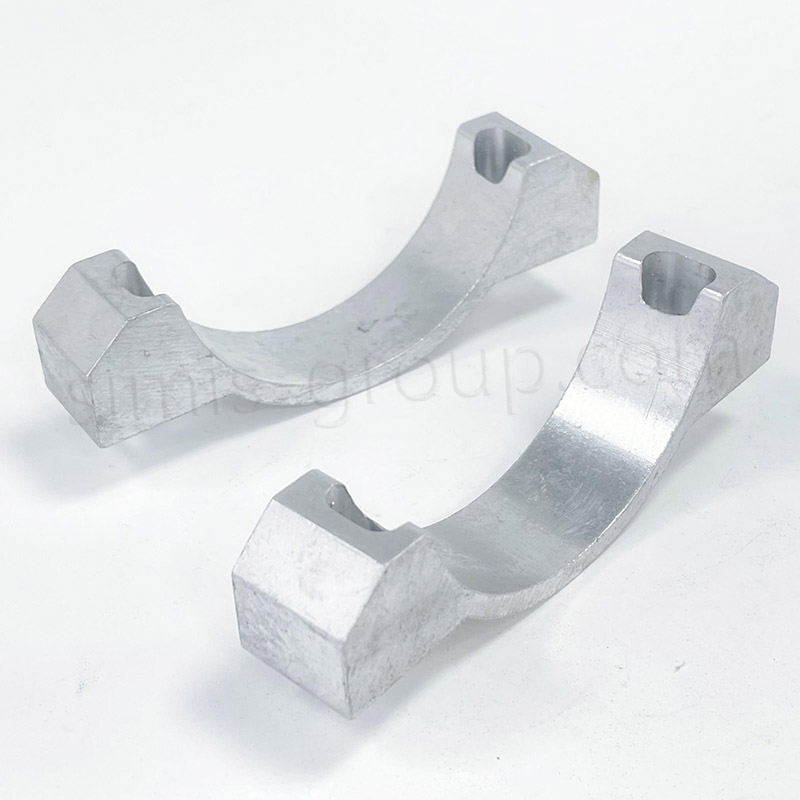
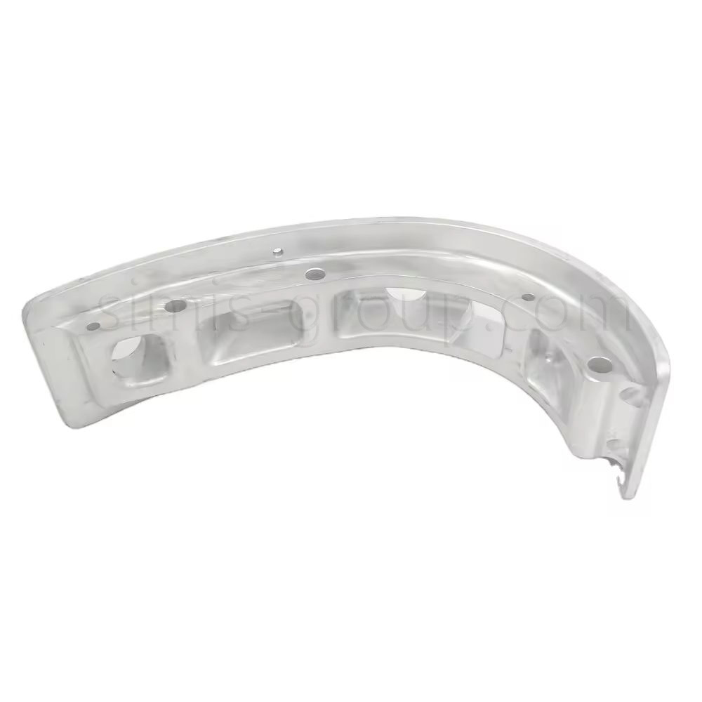
Shock Mount Bracket

Custom Shock Mount Bracket Manufacturing FAQs
Can SIMIS manufacture shock absorber mounting brackets to our drawings?
Yes. SIMIS supports drawing-based OEM production of metal shock mount brackets, frame mounting lugs and related shock absorber attachment components. Please provide a dimensioned 2D drawing or 3D CAD model, the mating shock eye or bushing geometry, expected load directions, material requirements and planned quantity. We review manufacturing feasibility before discussing tooling, machining and inspection.
Should a shock mount bracket be forged, cast or fabricated?
There is no universal process. Forged steel or wrought aluminum can be considered for compact brackets with demanding cyclic loads; ductile iron or cast steel may suit particular complex shapes when engineering validation permits. Cut-and-welded steel brackets can be efficient for plate-and-gusset structures. Geometry, weldability, expected production volume and required verification drive the selection.
Which dimensions matter most for shock absorber installation?
The mounting-hole diameter, bolt or pin fit, spacing between clevis ears, bushing sleeve width, ear parallelism, pivot-axis location and relationship to the chassis mounting datum are usually important. Clearance at full suspension travel must be assessed using the mating assembly. Only customer drawings and functional tolerance analysis can establish acceptable values.
Can you supply inspection reports or fatigue-tested brackets?
Dimensional inspection and material documentation can be planned against the agreed specification. If proof-load, fatigue, weld examination or non-destructive testing is required, the test method, sampling plan, acceptance criteria and responsible laboratory should be agreed before production. A manufactured bracket is not automatically certified for an entire vehicle or suspension system.
What should be included in an RFQ for custom shock mount brackets?
Send the part drawing or CAD file, assembly location, mating fastener and bushing details, material or load requirements, critical geometric tolerances, welding instructions if applicable, corrosion-protection finish, estimated annual volume and any prototype or first-article requirements. The more complete this information is, the more useful the initial manufacturability and cost review will be.
OEM Shock Absorber Mounting Brackets Made to Your Drawings
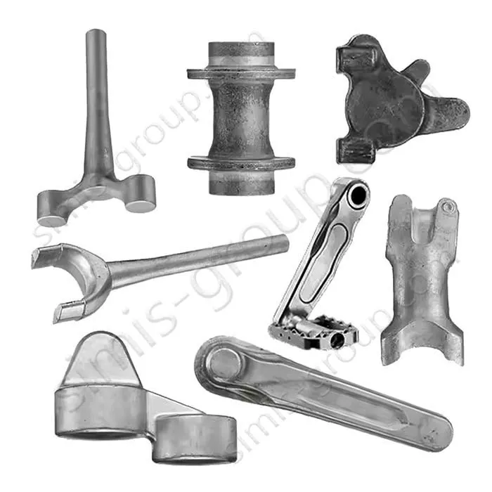
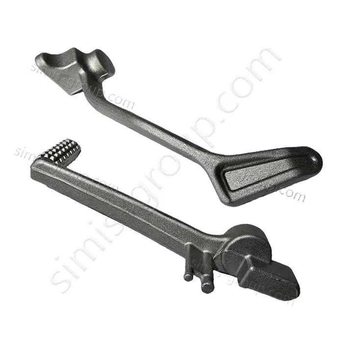
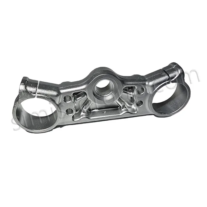
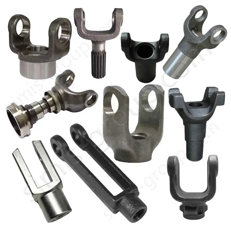
A shock mount bracket provides the structural interface between a shock absorber or damper eye and a vehicle frame, axle, swingarm or equipment structure. Although its envelope may be small, it must position the attachment accurately while carrying loads that can reverse direction and change rapidly during operation. The bracket itself is distinct from a suspension control arm: it supports the damper attachment rather than guiding wheel geometry through a ball joint or multiple pivots.
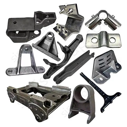
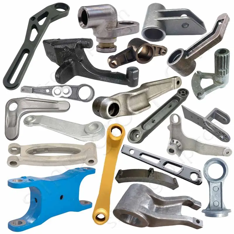
SIMIS handles custom brackets for trucks, trailers, agricultural machines, construction equipment and selected motorcycle or bicycle assemblies. The manufacturing route is evaluated against your design rather than offered as an off-the-shelf universal fitting. For assemblies using more extensive linkage geometry, our custom suspension control arms and custom link arms pages cover different types of motion-control components.
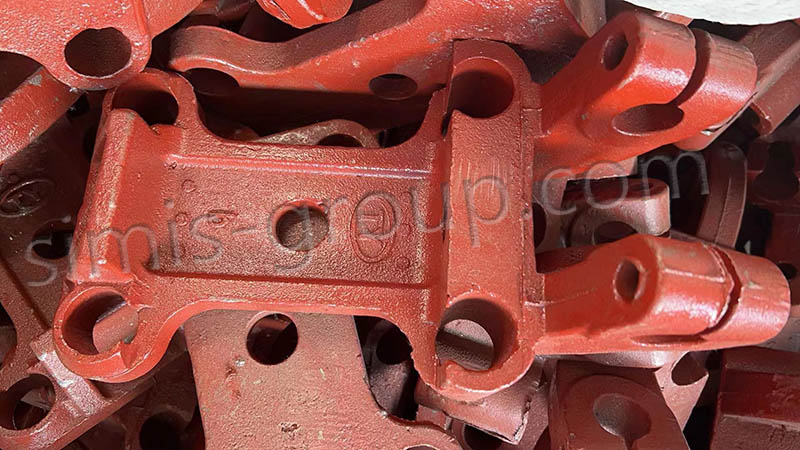
Shock Mount Bracket Designs and Load Paths
Double-shear clevis brackets and single-shear lugs
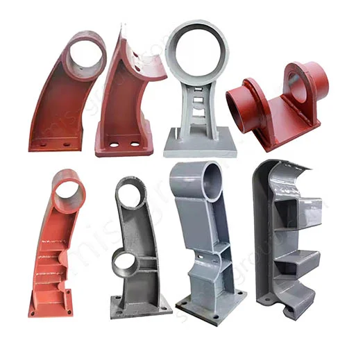
A double-shear clevis has two ears with a damper eye or bushing sleeve between them. Ear spacing and hole-axis alignment affect clamping and movement. A single-shear lug supports the fastener from one side and creates a different bending demand at the bracket and joint. Neither layout is inherently suitable for every duty cycle: bolt size, joint stack-up, load path and strength calculations must be established at the assembly level.
Frame, axle and swingarm mounting interfaces
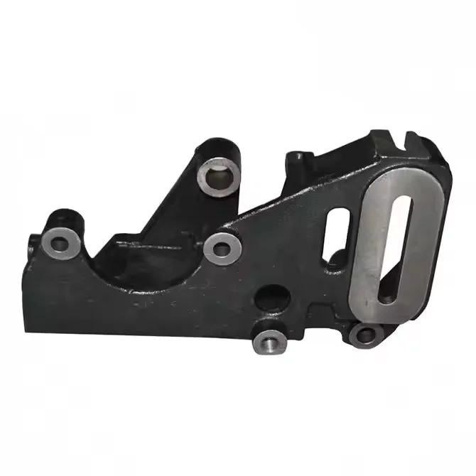
Some parts attach through machined bolt patterns, while others are welded into a chassis or axle structure. The design may also require support gussets, spacer bosses, service access and a specified damper angle. Bracket stiffness, contact with mating surfaces and avoidance of interference through the full stroke are important design-review topics. Related but different interfaces are found in custom engine brackets used to attach powertrain assemblies.
Pivot freedom and bushing stack-up
The shock absorber usually rotates through a limited angle around its mounting fastener. A bracket that pinches the wrong surface, traps the eye or loses clearance after coating can restrict motion. Control of the clevis gap, sleeve length, washer stack and bolt clamping arrangement therefore matters alongside the nominal hole diameter. Where bearings or spherical joints are specified, their manufacturer-defined mounting requirements take precedence.
Choosing Forging, Casting or Fabrication
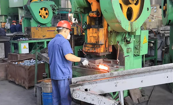
Selecting a process starts with the load path, geometry, production quantity and manufacturing constraints. The same nominal bracket shape can behave differently depending on alloy, heat treatment, internal material quality, weld design and surface condition. CNC machining is used where the functional interfaces need greater precision than the near-net-shape process alone can provide.
| Manufacturing route | When to evaluate it | Design considerations |
|---|---|---|
| Closed-die steel or aluminum forging | Compact mounting lugs or arms subject to significant repeated or impact loading | Parting line, draft, fiber flow, machining stock, material condition, tool investment |
| Sand or shell-mold casting | Cast-iron or cast-steel brackets with ribs, bosses or geometry difficult to fabricate | Wall transitions, feeding, shrinkage, casting soundness, critical machining allowances |
| Gravity permanent mold aluminum casting | Repeat-production aluminum shapes using an appropriate casting alloy | Draft, mold access, section uniformity, porosity controls; wrought alloys are not interchangeable with cast alloys |
| Cut, bent and welded steel plate | Brackets assembled from plates, clevis ears, tubes and reinforcement gussets | Weld access, fixture location, distortion, weld procedure and post-weld inspection |
| CNC machining of stock or near-net blanks | Prototypes, moderate volumes and precision attachment surfaces | Material waste, fixture datum strategy, bore and face tolerance requirements |
For forged structural options, see our closed-die forging capability. For complex ferrous bracket castings we assess sand casting, while gravity permanent mold casting may be considered for suitable cast-aluminum projects. Plate-and-gusset designs are better evaluated under sheet metal fabrication.
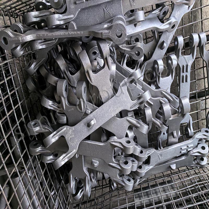
Selecting Materials for Strength, Toughness and Corrosion
A material grade should not be chosen from tensile strength alone. Shock mounts can see repeated bending, shear, impact and environmental exposure. Welded brackets also require attention to carbon equivalent, filler metal, joint geometry and heat-affected-zone properties. A heat-treated high-strength steel may not be an appropriate substitute for a readily weldable structural steel without reviewing the entire joint.
| Material family | Potential benefit | Points to confirm |
|---|---|---|
| Low-carbon structural steel | Useful for formed or welded mounting frames and brackets | Grade-specific weldability, section thickness, protective coating |
| Alloy steel forgings | Strength and toughness options where heat treatment is engineered | Fatigue demand, hardness, toughness, weld restrictions and machining |
| Ductile iron | Castability for ribs and bosses and useful mechanical properties by grade | Cast section properties, design allowables and application-specific validation |
| Cast steel | Complex structural shape with steel-like metallurgical options | Casting soundness, heat treatment, weld repair approvals where applicable |
| Wrought or cast aluminum alloy | Low mass for selected motorcycle, bicycle or vehicle mounting structures | Correct wrought-versus-cast grade, corrosion, fatigue and galvanic pairing |
| Stainless steel | Corrosion resistance for suitable outdoor or washdown environments | Grade, strength, galling, welding and mating-fastener compatibility |
Where a project requires controlled properties, heat treatment may be incorporated into the manufacturing plan. Final grade and condition are set by the customer’s drawing or an approved alternative, not by a blanket promise of a particular number of fatigue cycles.
Critical Dimensions for Shock Mount Bracket Machining
Mounting holes, pivot bores and coaxial alignment
The pivot bore must accommodate the specified bolt, pin, sleeve or bearing interface. For two-ear brackets, the holes should be controlled with reference to the intended common pivot axis, not simply checked as two unrelated diameters. Hole location relative to the chassis datum can also be critical to shock absorber angle and packaging. Some designs require finished reaming or boring after casting, forging or welding.
Clevis gap, ear parallelism and mounting faces
An undersized clevis gap can clamp the damper eye instead of its inner bushing sleeve; excessive spacing can demand an unapproved washer stack or create bending in the joint. Parallel ear faces, bracket mounting pads and bolt-hole patterns therefore belong on the critical-feature list where they affect assembly. For welded steel units, finish-machining after weld distortion may be appropriate, depending on the tolerance scheme.
Datums, geometric tolerances and inspection access
A practical drawing defines the surface or bolt pattern that locates the bracket in its host structure, then relates the pivot axis and other features to that datum. This avoids unnecessary blanket tolerances while giving inspection personnel clear criteria. SIMIS can review fixture location, drill access and CMM or gauge inspection strategies as part of CNC machining planning.
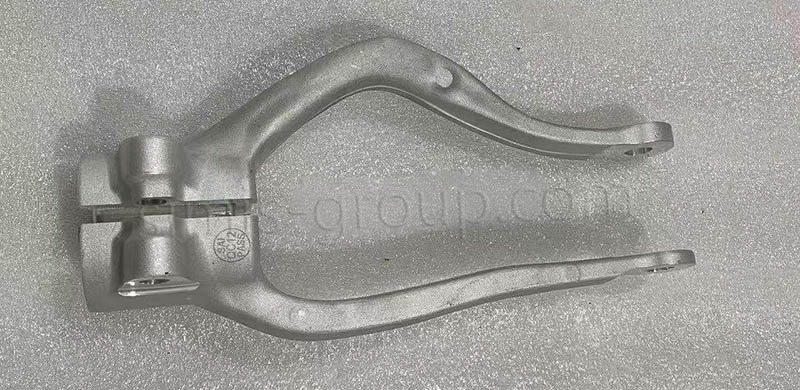
Designing for Repeated Loads and Fatigue
Shock absorber brackets experience forces from the suspension and damper, including reversals during bump and rebound. Depending on the installation, off-axis loads and shock events can be as important as the largest steady load. Likely high-stress regions include ear roots, weld toes, sharp section transitions, locally thin walls and holes close to free edges.
Manufacturing considerations include generous geometry transitions where the engineering drawing allows, repeatable heat-treatment condition, consistent weld termination, controlled porosity in castings, and avoidance of damaged machined surfaces. These measures support a controlled component, but they do not replace design calculations, vehicle-level validation or the fatigue test requested by the OEM. Proof load, cyclic load spectrum, required sample quantity and rejection criteria must be defined before performance claims can be made.
Welded Shock Mount Brackets and Assembly Control
When the design uses fabricated steel plates or lugs, weld accessibility and the order of operations strongly affect cost and dimensions. Welded ear pairs can draw inward as the joint cools, moving the pivot-hole centerline or closing the clevis gap. Depending on the drawing, suitable manufacturing methods may include locating fixtures, balanced weld sequences, intermediate dimensional checks and final machining of the pivot interfaces.
The welding specification should identify base metals, any filler requirements, weld size and location, and inspection criteria. The bracket’s load rating cannot be inferred from weld appearance alone. Where the component will be welded by the equipment manufacturer, it is important to clarify whether SIMIS is supplying a raw bracket, a prepared weldment or a fully finished assembly. That decision changes the needed material condition, surface finish and acceptance plan.
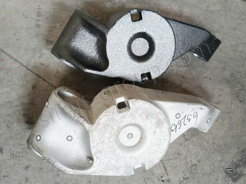
Surface Protection and Finished-Part Compatibility
Typical choices may include primer and paint, powder coating, zinc-based coatings, or selected conversion and anodizing treatments for compatible aluminum alloys. The finish should be chosen against salt exposure, abrasion, mating-metal corrosion and the required visual appearance. Masking or rework may be necessary at precision pivot bores and bearing seats so that coating build-up does not change the installed fit.
Our surface treatment options can be discussed together with the part drawing. Any salt-spray duration, coating thickness, adhesion result or corrosion-life target must be stated in the project specification and demonstrated by the agreed test method if required.
Quality Control for OEM Shock Mount Brackets
Inspection focuses first on the features affecting assembly and traceability: material identification, mounting-hole position, bore size, clevis width, datum-to-pivot geometry, surface condition and the agreed coating specification. For cast or forged parts, additional checks may be necessary around high-load sections, depending on the design assessment. A first-article layout is useful when establishing tools and fixtures before repeat production.
| Inspection topic | Possible method | What the drawing or agreement should define |
|---|---|---|
| Critical dimensions and geometry | CMM, gauges, calibrated measuring equipment | Datums, bore size, true position, gap and inspection frequency |
| Raw material and heat treatment | Material records, chemistry, hardness or mechanical tests where requested | Specified material grade, condition and lot traceability |
| Cast, forged or welded regions | Visual checks; MT, PT, UT or other NDT if selected | Locations, standard, acceptance class and sampling plan |
| Surface finish and corrosion coating | Appearance and thickness checks; project-specific coating tests | Coating system, excluded areas and acceptance criteria |
| Load and fatigue verification | Proof-load or cyclic testing by an agreed laboratory or setup | Load direction, fixtures, cycles, sample plan and pass/fail requirements |
SIMIS presents its broader inspection practices on our quality control page. No single inspection method, automotive standard or fatigue-cycle count applies automatically to every bracket. Project-specific approvals such as PPAP or other production documentation should be requested during RFQ review so the scope and responsibility are clear.
Applications and Boundaries of the Product
Shock mount brackets may be used on commercial trucks, trailers, agricultural implements, off-road machinery and selected motorcycles or bicycles. The geometry can range from compact clevis lugs to larger frame-attached parts with integral ribs. Some applications prioritize low mass; others require weld compatibility, corrosion protection or serviceability. In every case, the mating shock eye, fastener, host frame and operating load spectrum determine whether the component design is appropriate.
This page addresses manufacturing the bracket according to an approved drawing. It does not represent a complete shock absorber, suspension linkage, or certified vehicle attachment kit. Similarly shaped brackets may not be interchangeable between vehicles without engineering review.
Request a Quote for Custom Shock Mount Brackets
For an efficient manufacturing review, send a 2D drawing with tolerances and a 3D model where available; identify the bracket location, mounting bolt or pin, bushing sleeve width, operating environment and expected load or fatigue specification. Please include material and heat-treatment requirements, the desired finish, welding or assembly instructions, estimated batch/annual quantity, and any first-article or test documents required by your OEM program.
SIMIS can review the proposed blank-making route, tool requirements, functional bore machining, finishing and agreed inspection scope, then prepare a project-specific quotation. Email your drawing to info@simis-group.com or use the inquiry form on this product page.