Custom Universal Joint Fork Manufacturer
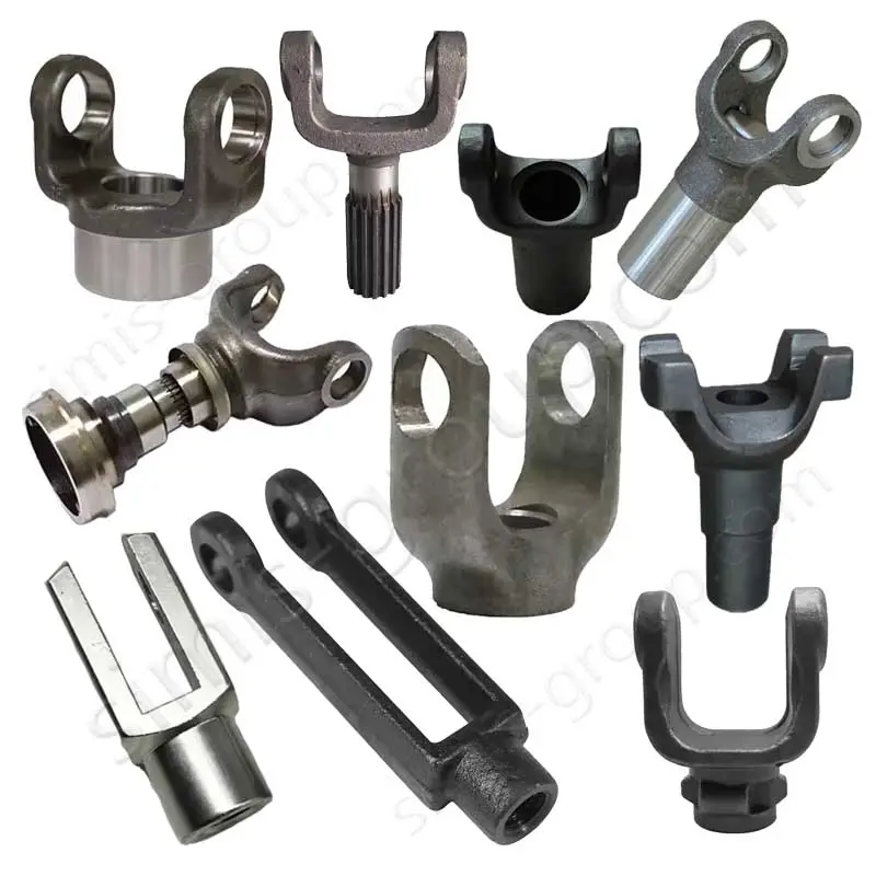
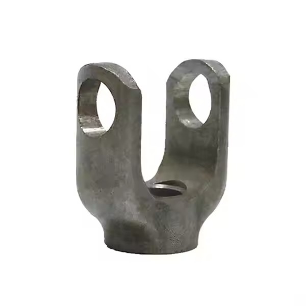
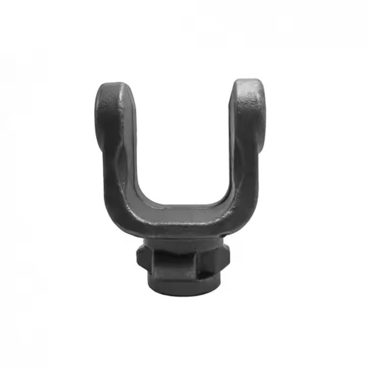
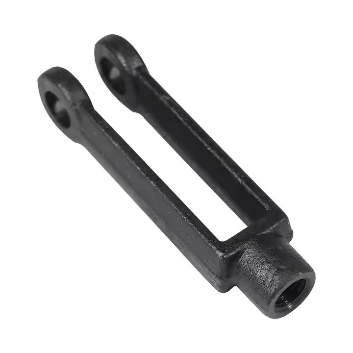
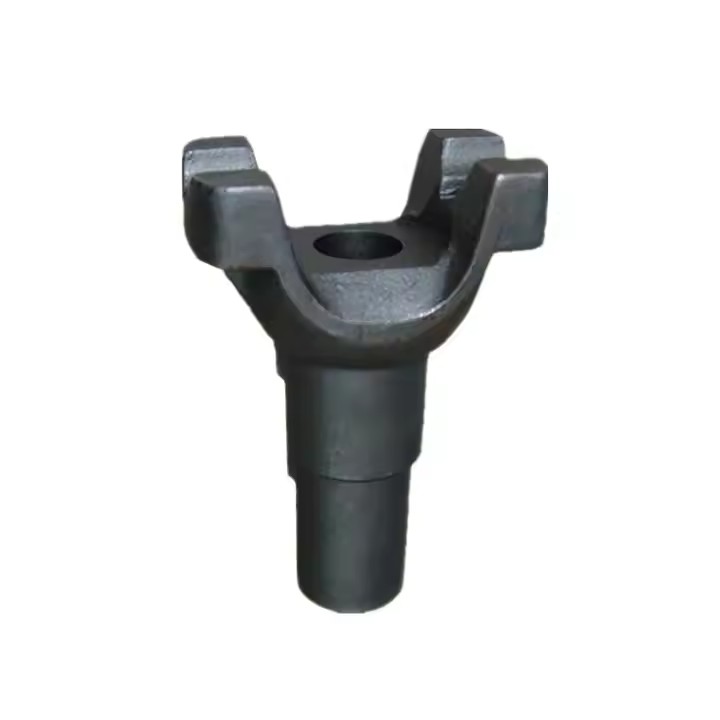
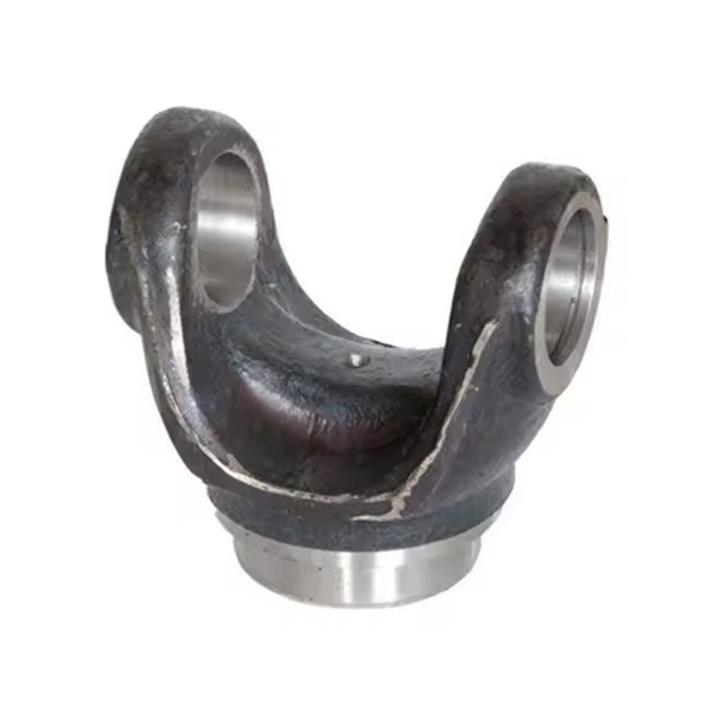
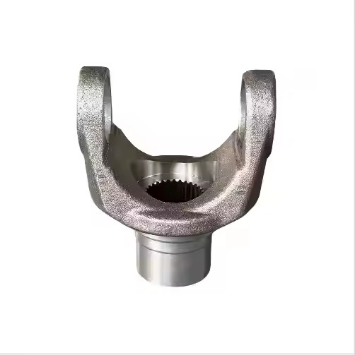
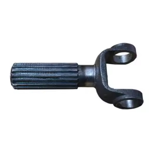
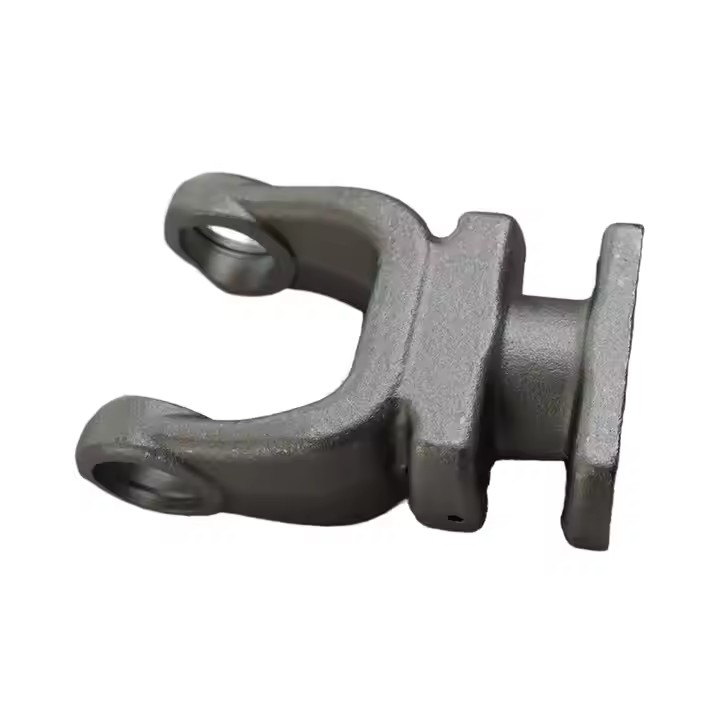
Universal Joint Fork

Custom Universal Joint Fork Manufacturing FAQs
Can SIMIS manufacture universal joint forks from our drawings?
Yes. SIMIS supports OEM universal joint fork and yoke components made to customer-provided 2D drawings, 3D CAD models and technical specifications. The manufacturing route is evaluated against the fork geometry, intended torque and speed, material requirements, order quantity and the critical mating interfaces. These are custom metal components rather than an interchangeable inventory of finished universal joint assemblies.
Should a U-joint fork be forged or cast?
Closed-die steel forging is often considered for yokes exposed to substantial torque reversals, shock loads or repetitive loading. Steel investment casting may be appropriate for intricate shapes, while qualified ductile-iron castings may suit selected industrial designs. No single process is universally preferable: the decision depends on the drawing, material properties, component size, production volume and validation requirements.
Which dimensions are most important on a universal joint fork?
Typical drawing priorities include the bearing cup bore diameter and roundness, alignment of the opposed bores, distance between the yoke ears, retaining-ring or snap-ring location where applicable, and the relationship between the cross-axis and the connecting shaft, spline or flange. The actual datum scheme and tolerances must be specified for the mating universal joint design.
Can you provide heat treatment, machining and inspection?
SIMIS supports an integrated manufacturing route with casting or forging, CNC machining, project-specific heat treatment, surface finishing and inspection. Chemical composition checks, hardness measurements, dimensional reports or non-destructive testing can be specified as appropriate to the agreed inspection plan; these tests should not be assumed to apply to every part without an agreed requirement.
What information is needed for an OEM quotation?
Provide the drawing or CAD model, material grade, expected annual quantity, bearing cup size, mating joint arrangement, connection details, load and rotational-speed information, and any heat treatment or inspection specifications. Indicate whether you need a bare fork, a machined yoke, or a component prepared for subsequent drivetrain assembly.
What Is a Custom Universal Joint Fork?
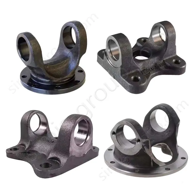
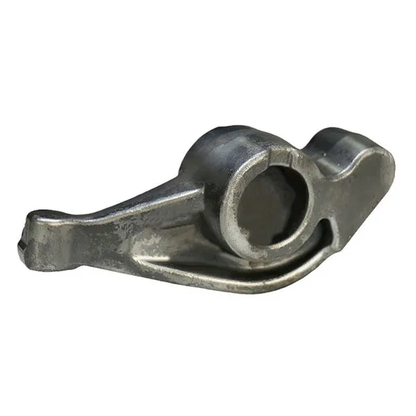
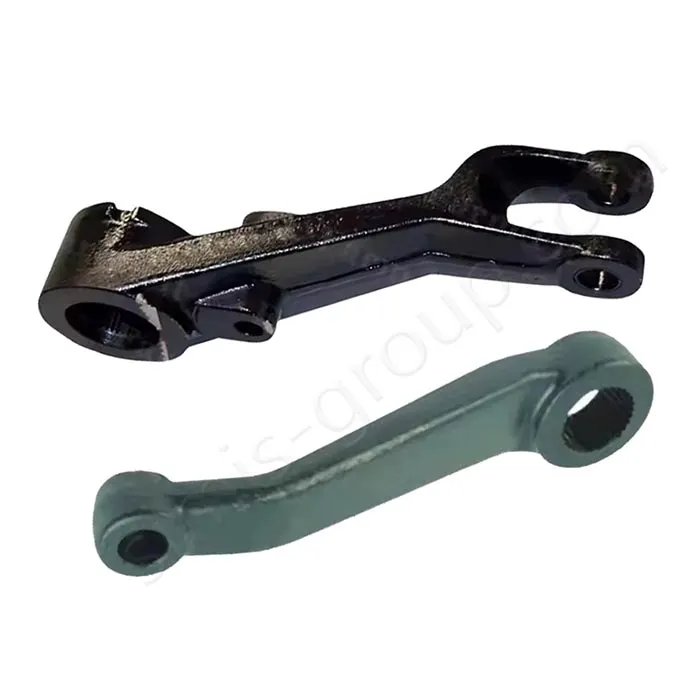
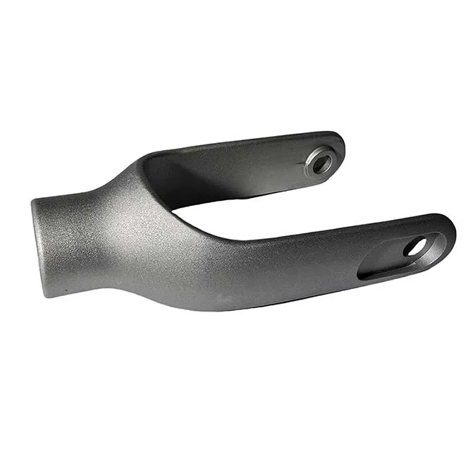
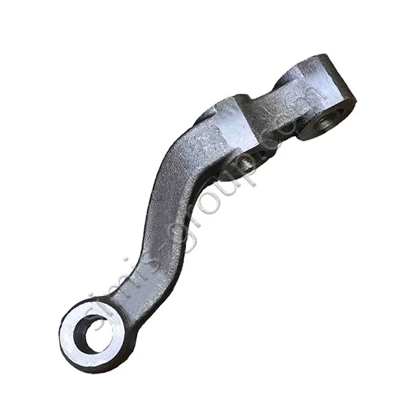
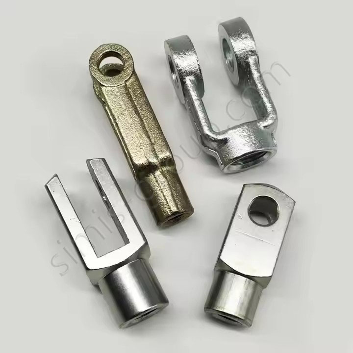
A universal joint fork, also called a U-joint yoke, is the clevis-shaped part that receives a universal joint cross and its bearing cups. Together with the matching yoke and cross assembly, it permits torque transmission between shafts that operate at an angle. Its function depends on accurate bearing support, robust fork arms and a secure connection to the remainder of the drivetrain.
Depending on the application, the interface may be a splined hub, a keyed connection, a tube-weld end or a bolted flange. A universal joint fork is therefore not the same as a complete U-joint, and different end yokes, weld yokes and flange yokes should not be treated as interchangeable simply because they share a fork-shaped profile.
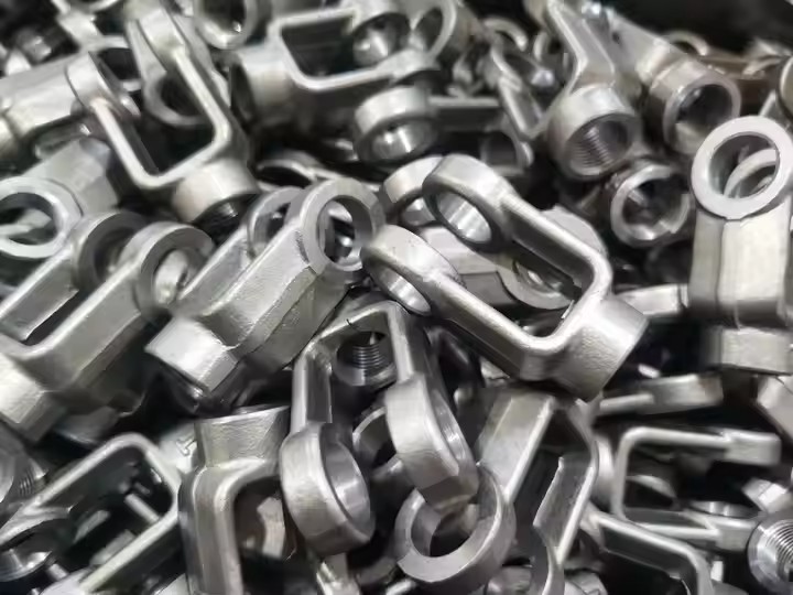
For OEM programs, SIMIS reviews the supplied geometry to establish the workable blank-making process, machining sequence and inspection points before agreeing on a production specification.
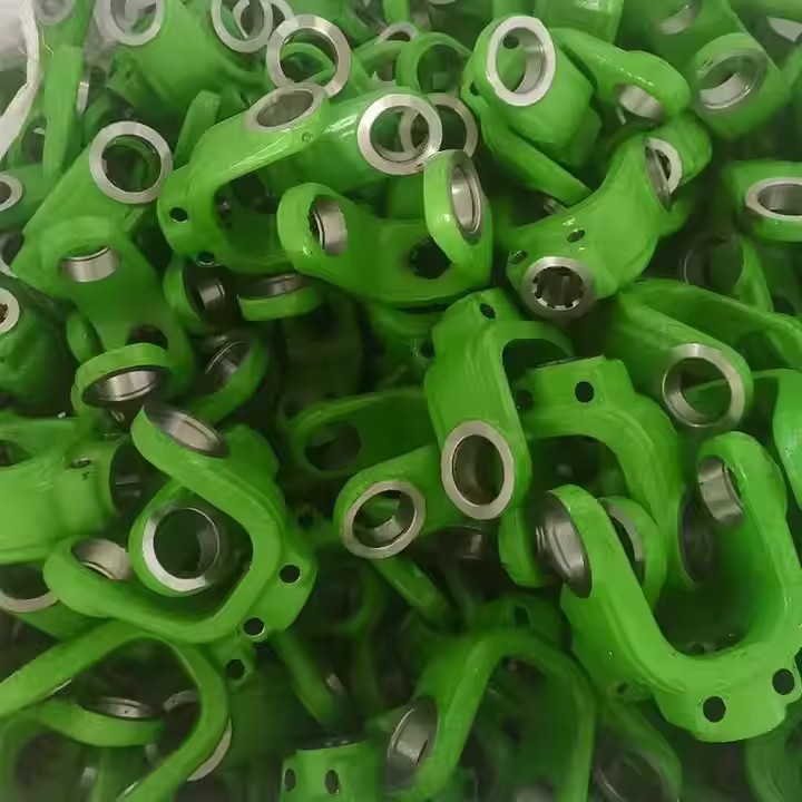
Forging, Investment Casting or Sand Casting: Choosing the Right Route
The choice of blank-making process is a structural and commercial decision. Bearing cup bores and other functional surfaces generally receive subsequent machining; the as-forged or as-cast shape alone should not be presented as a finished precision joint interface.
| Manufacturing route | Where it can fit | Important engineering considerations |
|---|---|---|
| Closed-die steel forging | Recurring high-load applications and suitable production volumes | Tooling cost, grain-flow direction, radii at the ears, machining stock and heat treatment |
| Investment casting | Special geometry in steel or stainless steel where a near-net-shape blank is valuable | Casting integrity, section changes, mechanical properties and machined bore allowances |
| Sand or shell mold casting | Selected larger industrial yokes, often with a qualified cast-iron or cast-steel design | Section thickness, solidification behavior, machining stock and application-specific loading |
| Machining from solid stock | Prototype or low-volume geometries when material utilization and cycle time are acceptable | Material waste, access to internal shapes, fixturing and fatigue-critical transitions |
Forged steel U-joint forks
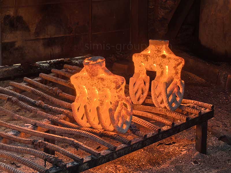
For suitable shapes and quantities, closed-die forging produces a shaped steel blank for subsequent critical machining. Forging can help develop favorable material flow and mechanical properties, but the final outcome also depends on steel grade, die design, heat treatment, process control and part geometry. A percentage improvement in fatigue life cannot be inferred without a defined comparison and test data.
Precision-cast and larger industrial yokes
Our investment casting route may be reviewed for complex alloy-steel or stainless-steel configurations. For appropriately engineered industrial designs, sand casting and shell mold casting are additional options. The required strength, inspection class and loading history must be considered before substituting a cast blank for a forged component.
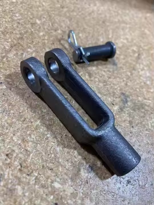
Material Selection for Torque, Impact and Corrosion
Material selection should be based on the specified mechanical properties and service environment, not just the nominal alloy name. Carbon and low-alloy steels can be used for forged yokes; stainless steels address selected corrosive exposures; ductile iron or cast steel may be appropriate for applications designed around cast components. SIMIS can review customer-specified grades and alternatives during the manufacturing feasibility assessment.
| Candidate material | Potential advantage | Points to confirm |
|---|---|---|
| Medium-carbon steel | Useful combination of cost, machinability and achievable mechanical properties | Heat-treatment condition, section size, toughness and fatigue requirements |
| Low-alloy steel such as 42CrMo4 / AISI 4140 | An option where strength and hardenability are important | Specified properties, quench response, hardness range and joint loading |
| Stainless steel | Resistance to selected corrosive environments | Correct stainless grade, strength in the supplied condition and machining behavior |
| Ductile iron or cast steel | Possible casting options for geometry and quantity requirements | Approved design, casting soundness, fatigue loading and project qualification |
The steel forging service provides context on carbon and alloy steel forming options. Any alternate material proposal must be reviewed against the client drawing and assembly duty; a grade should never be substituted based on similarity of appearance or nominal hardness alone.
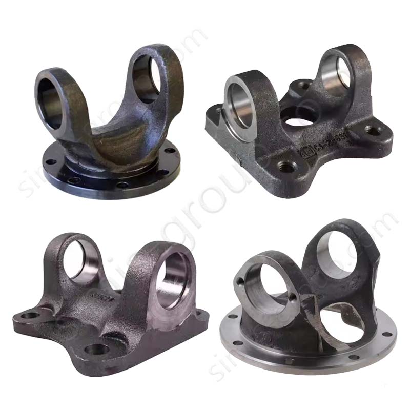
Critical CNC-Machined Features of a U-Joint Yoke
Opposed bearing cup bores and common cross-axis
The bearing bores hold the needle-bearing cups of the joint cross. Their finished diameters, roundness and relative alignment influence cup retention and the freedom of movement of the cross. The opposed bore axes must be controlled relative to the defined joint geometry; the correct drawing requirement may involve coaxiality, position and geometric tolerances rather than a generic promise of “micrometer precision.”
Fork-ear spacing, thickness and retaining features
Ear spacing must accommodate the selected cross and bearing cups, including any internal or external snap rings. Fork-ear thickness, local stiffness, groove geometry and edge condition also matter. Machining and inspection should reflect whether the customer design uses pressed-in cups, circlips, lock plates or another approved retention arrangement.
Shaft, spline, keyway or flange connection
The fork transmits torque into the next shaft or mounting interface. Where present, spline form, keyway geometry, pilot diameter, bolt-circle location, hub-to-cross alignment and flange runout require defined datum relationships. Related shaft flange yoke designs may share manufacturing methods but use different installation interfaces.
Transitions, fillets and surface condition
Abrupt section changes at the ears, neck and hub can concentrate stress. Suitable fillets, controlled machining marks and adequate material around bearing bores should be reviewed during DFM. These details are significant in reversing torque and cyclic-load applications, but the required fatigue performance must come from customer engineering requirements and validation.
From Drawing to Finished U-Joint Fork: OEM Workflow
A reliable manufacturing plan begins with the functional features of the part. Rather than selecting a process first and then forcing the drawing to fit it, SIMIS can assess which surfaces can be left in the blank condition and which must be machined from consistent datums.
Drawing and DFM review: examine joint series, bearing cup dimensions, nominal shaft axis, fork openings, load path, corner radii and tooling access.
Blank route and tooling: select forging or casting, consider draft and parting lines, and reserve suitable machining allowance at the cup bores and hub interface.
Material and heat treatment: establish the requested grade, property targets and when any heat treatment should occur in the sequence.
Functional machining: use appropriate setups for the opposed bores, retaining features, pilot or spline, and controlled mating surfaces.
Verification and release: inspect the dimensions and material characteristics specified in the drawing and approved control plan.
The CNC machining stage is planned around repeatable location of the fork rather than around the external shape alone. For some geometries, rough-machining before heat treatment followed by finish-machining may be appropriate to manage distortion; the sequence is reviewed case by case.
Heat Treatment, Hardness and Surface Protection
Heat treatment is used where the material specification calls for particular strength, toughness or wear characteristics. Depending on the grade and design, normalizing, quenching and tempering or other qualified treatments may be considered. High surface hardness is not automatically desirable at every location: a fork subjected to impact or alternating torque also needs appropriate core behavior.
Our metal parts heat treatment capability can be considered when the approved specification calls for it. After machining, surface treatment options may include protective coatings or other customer-approved finishes; bore fits, splines, retaining grooves and mating faces may need masking or post-coating dimensional checks.
Inspection: What Should Be Verified on a Universal Joint Fork?
A clear inspection plan separates features of the supplied yoke from performance of the assembled universal joint or driveshaft. Acceptance is based on agreed drawings, standards and sample or production control plans, not on an implied universal test package.
| Inspection item | Typical verification approach | Why it matters |
|---|---|---|
| Bearing cup bores and retaining features | Bore gauges, suitable geometric measurement or CMM, as specified | Bearing cup fit and consistent cross assembly |
| Fork geometry and connection interface | Ear spacing, cross-axis relationship, flange or spline features against drawing datums | Assembly alignment and torque-transfer interface |
| Material and heat-treatment condition | Material documentation, chemistry or hardness testing as required | Conformance with the approved material specification |
| Surface and subsurface integrity | Visual inspection; MPI, UT or other NDT only where specified and applicable | Verification against agreed defect acceptance criteria |
| Load and rotating performance | Project-defined proof, fatigue or assembly balance verification when required | Performance depends on the complete design and assembled system |
Additional details on inspection methods are available through SIMIS quality control information. A single fork is not automatically dynamically balanced as a complete rotating shaft; assembly-level balancing should be specified separately where shaft speed and application require it.
Applications in Automotive, Agricultural and Industrial Drivetrains
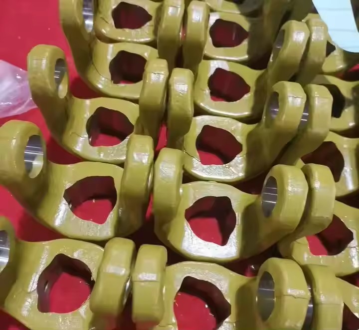
Universal joint yokes appear in vehicle propeller shafts, agricultural PTO arrangements, machinery transmission shafts and other joints that must transmit rotary motion through an angular offset. The required design differs greatly between a high-speed road-vehicle driveline and a low-speed industrial coupling.
For automotive and truck use, mounting geometry, rotational speed, reversal of torque and joint series typically govern the drawing. Construction and mining applications may emphasize shock loading, equipment fit and harsh environmental exposure. In agricultural machinery, operating angle, wear conditions and serviceability can be important. None of these application labels alone establishes an acceptable material, safety margin or fatigue-test requirement.
DFM Review and RFQ Checklist for Custom Universal Joint Forks
For a useful quotation, the customer should identify which part of the assembly is being ordered. The same term “U-joint fork” can describe different end connections and bearing-retention styles. Clarifying the configuration early helps avoid quoting the wrong tooling or inspection approach.
Geometry: dimensioned 2D drawing and preferably a 3D model, showing fork ears, bearing cup bores and mating-interface features.
Joint and connection: bearing cup series or dimensions, retaining method, shaft or tube interface, splines, pilot and bolt pattern as applicable.
Material and treatment: material grade, heat-treatment condition, protective coating and areas where coating is restricted.
Operating conditions: torque range, torque reversal, speed, operating angle, impact exposure and corrosive or abrasive environment if known.
Acceptance and volumes: critical dimensions, applicable specifications, testing or documentation needs, prototype quantity and annual forecast.
A related custom drive shaft may require additional assembly-specific data such as tube specification, joint phasing, overall length and balance class. These requirements are not automatically part of a single U-joint fork quotation.
Request a Custom Universal Joint Fork Manufacturing Quote
Send your universal joint fork drawings and RFQ details to info@simis-group.com. SIMIS can review a suitable forming route, machining requirements, material and heat-treatment specifications, inspection scope and the information needed for a project quotation. Manufacturing feasibility and any project-specific mechanical performance claims are confirmed against the supplied engineering requirements before order acceptance.