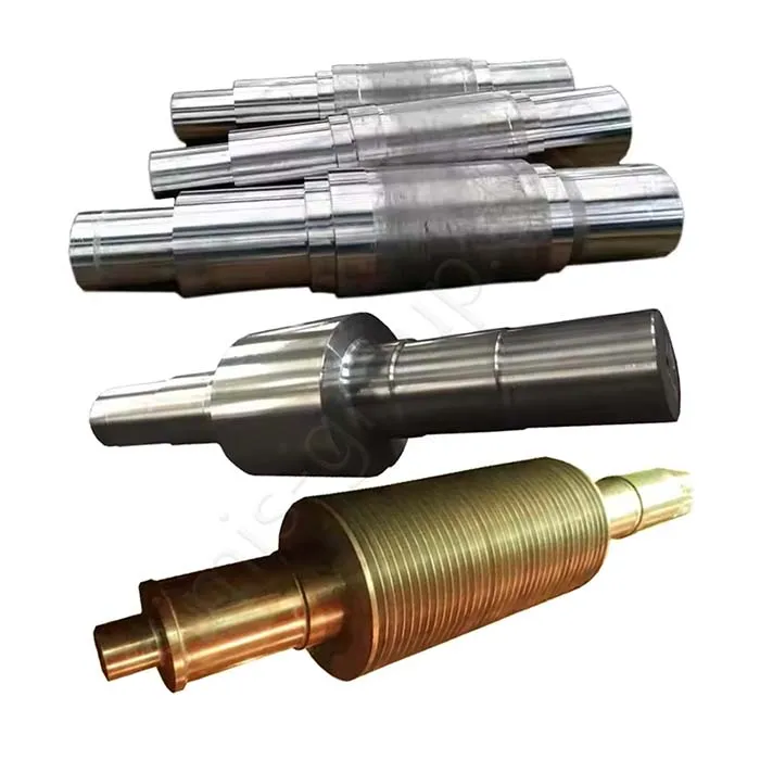
Custom Screw Conveyor Roller Spiral Shaft Manufacturer
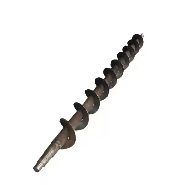


Screw Conveyor Roller Spiral Shaft

Custom Screw Conveyor Spiral Shaft Manufacturing FAQs
Can SIMIS manufacture screw conveyor spiral shafts from OEM drawings?
Yes. SIMIS reviews customer 2D drawings and 3D CAD models for custom screw conveyor shaft cores, spiral-flight assemblies, coupling features, bearing journals and associated metal components. Depending on the design, production may involve a forged or machined shaft, formed and welded flighting, precision turning and specified inspection. We manufacture to project drawings rather than offering a universal stocked replacement shaft.
Is forging always necessary for a screw conveyor roller spiral shaft?
No. A heavily loaded solid shaft may justify an open-die forged steel blank, while smaller solid shafts can sometimes be machined from bar stock. Tubular screw assemblies commonly use a tube with formed flighting attached by welding. Coupling hubs may be machined or forged separately. Geometry, torque, span, material, batch quantity and downstream welding determine the practical route; forging the core does not mean the entire helical flight assembly is forged.
What dimensions are important for a custom screw conveyor shaft?
The drawing should define the outer flight diameter, shaft or tube diameter, total length, flight pitch and hand (right- or left-hand), flight thickness and profile, and any variable-pitch sections. Bearing-journal positions, coupling geometry, keyways, bolt patterns, straightness and runout criteria are equally important for assembly fit. The required clearance to the trough or casing is an equipment design input, not a universal tolerance.
How can straightness, concentricity and weld distortion be managed?
The manufacturing plan can establish datums at shaft ends or bearing seats, apply controlled fixturing during flight attachment, and include intermediate straightness and runout checks. Welding sequence, section thickness and overall length influence distortion. Final machining of selected journals or couplings may be appropriate after fabrication, depending on drawing requirements and available machining allowance.
What information is needed for a screw conveyor shaft quotation?
Please provide dimensional drawings or CAD files, material specification, shaft length, flight outside diameter and pitch, the conveyed medium, estimated torque or operating duty, speed, interface dimensions and order volume. Also identify abrasion or corrosion exposure, required testing, whether flights must be assembled to the shaft, and whether the purchase scope includes couplings or bearing supports.
OEM Screw Conveyor Roller Spiral Shafts Made to Drawing
A screw conveyor shaft transmits rotary motion to a helical flight that moves bulk material through a trough or enclosed casing. Unlike a conventional power-transmission shaft, its critical geometry also governs how the flight runs relative to the casing and adjacent screw sections. Shaft length, overhung load, flight arrangement and the properties of the conveyed material all affect manufacturing choices.
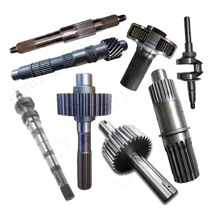
SIMIS focuses on custom metal components for equipment manufacturers, including shaft cores, end shafts, coupling pieces and fabricated spiral assemblies where defined in the customer scope. For related shaft manufacturing examples, see custom drive shafts and custom support shafts. These have overlapping machining requirements but different functional design priorities.

Key Dimensions and Engineering Requirements for Screw Conveyor Shafts
For a reliable quotation, the part drawing should describe both the shaft interfaces and the geometry of the helical flighting. The following parameters are especially useful when reviewing manufacturability.
| Feature on the drawing | Why it matters to manufacturing |
|---|---|
| Overall shaft length and segment length | Influence material stock, workholding, deflection and whether a segmented assembly is more practical. |
| Flight outside diameter (OD) and root/shaft diameter | Set the flight geometry, clearance envelope and potential fabrication route. |
| Flight pitch, hand and number of starts | Define spiral geometry and the direction of intended material transport; variable-pitch or multi-start designs require explicit drawings. |
| Flight thickness and profile | Affect forming, weld access, rigidity and wear allowance; full-flight, ribbon or cut-flight designs are not interchangeable. |
| End journals, flanges and couplings | Determine bearing fit, torque-transfer interfaces, mating dimensions and critical machined datums. |
| Runout, straightness and assembly clearance | Identify how fabricated geometry should be measured and how the completed screw fits its casing or trough. |
| Operating speed, torque and service medium | Guide material, connection and inspection requirements, especially for abrasive, corrosive or intermittent-duty service. |
The equipment designer should specify any applicable mechanical calculations, allowable deflection and functional acceptance tests. The shaft manufacturer can then review which values can be produced and inspected at component level.
Selecting the Manufacturing Process: Forging, Fabrication and CNC Machining
Open-Die Forged Steel or Machined Solid Shaft Cores
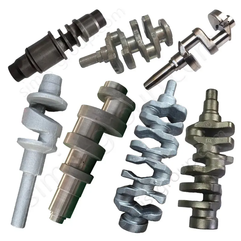
For large-diameter or demanding solid shaft designs, open-die forging can be evaluated as a way to prepare a steel preform with suitable machining stock. Forged blanks require grade-specific processing, material verification and allowance for the finished journals and shoulders. For less demanding dimensions or shorter production runs, machining from certified bar stock may be more economical. The drawing, not a generic strength claim, determines whether forging is justified.
Formed Flighting and Welded Screw Assemblies
A typical screw conveyor flight is formed from plate or other suitable metal stock and joined to a shaft or tube. Pitch consistency, flight concentricity, weld access and distortion control are important throughout assembly. Metal fabrication methods can support appropriate cutting, forming and joining tasks. Whether the final assembly is a solid-shaft screw, tubular screw or removable flight arrangement must be defined before quotation.
Forged or Machined Coupling Hubs and End Connections
Some designs use separate coupling shafts, flange hubs or driving ends. closed-die forging may be considered for suitable repeated components, while smaller quantities may favor machined steel stock. Connection design must address the specified load path, key or spline fit, and access for assembly and future service.
CNC Turning and Finishing for Precision Interfaces
CNC machining is used where the drawing calls for defined shaft diameters, shoulders, threads, bearing seats, keyways or mating faces. Depending on shaft length and starting condition, the machining plan may include rough turning, reference-datum preparation, final turning and selected grinding. Not every surface needs a high-precision finish; critical functional interfaces should be identified explicitly.
Material Options for Custom Screw Conveyor Shaft Components
Material selection depends on the transported product, ambient conditions, structural loads, cleaning requirements and expected duty cycle. The materials below are engineering candidates to evaluate, not automatic substitutes for customer-specified grades.
| Material option | Potential use | Selection considerations |
|---|---|---|
| Carbon steel, including specified 1045 grades | General-purpose solid shaft cores and machined connectors | Strength requirements, weldability of chosen grade and operating conditions; a lower-carbon weldable grade may be more appropriate for some fabricated assemblies. |
| Alloy steel, such as specified 4140 or 42CrMo4 | Highly loaded solid shafts and selected coupling components | Mechanical property requirements, condition of supply, machining sequence and suitability for any welded construction. |
| 304 / 304L stainless steel | Corrosion-resistant screw and shaft components in suitable service | Cleaning chemistry, exposure, fabrication requirements and applicable hygienic specifications. |
| 316 / 316L stainless steel | Selected chemical, wet-processing or corrosion-exposed applications | Actual fluid chemistry and chlorides; material grade alone does not establish food-equipment certification. |
| Wear-resistant steel or abrasion-resistant flight plate | Flight surfaces exposed to severe abrasive bulk solids, where suitable | Formability, weld procedure, section thickness and replacement strategy. |
For stainless assemblies, the material used for the central shaft, flights and weld consumables should be reviewed together. In food or pharmaceutical service, hygienic design, cleanability and certification requirements belong in the OEM specification; stainless steel alone is not evidence of approval for food-contact use.

Dimensional Inspection, Shaft Straightness and Fabricated Assembly Checks
The inspection plan should concentrate on measurable characteristics that affect installation and operation. For custom screw conveyor roller spiral shafts, relevant checkpoints may include:
Material records: requested chemical or mechanical test documentation for the selected metal grade.
Overall geometry: completed shaft length, flight diameter, pitch, hand and any specified transition sections.
Shaft alignment: straightness and total indicated runout (TIR) referenced to the agreed datums or bearing seats.
Machined interfaces: journal diameters, concentricity, keyways, couplings and end-face relationships.
Fabricated joints: specified weld size, joint location and any required visual or non-destructive examination.
Assembly checks: requested fit, rotation or balancing verification, when within the purchase scope.
Ultrasonic, magnetic-particle or other non-destructive examination may be specified for particular shaft blanks or welded features; it should not be assumed necessary or performed on every product. Likewise, dynamic balancing is a design-dependent requirement, especially for higher-speed assemblies, and differs from dimensional runout measurement. Testing scope and acceptance criteria should be agreed before production.

Screw Conveyor Shaft Designs and Industrial Applications
Continuous and Segmented Conveyor Shafts
Continuous shafts may simplify the connection arrangement for shorter conveyors, provided their length and handling requirements are practical. Long conveyors may use multiple screw sections connected through specified couplings and supported at suitable locations. Segmented design can assist transport and servicing, but it introduces additional alignment and joint requirements that must be controlled.
Agriculture, Mining, Chemical Processing and Material Handling
Agricultural conveying may involve grains, feed and fertilizer; mining and construction systems may handle abrasive minerals, cement and ash. Chemical and wastewater systems can introduce corrosion or sticky materials, while food-processing equipment can require additional cleanability specifications. In each case, the conveyed medium affects material selection and flight wear considerations, but final throughput and operating performance are determined by the complete conveyor design. Explore agricultural machinery components, mining equipment metal parts and industrial machinery parts for related OEM manufacturing applications.
For a different type of spiral shaft operating with tighter contact and cleaning constraints, see our custom ice machine auger components page. Although both use helical geometry, they must not be manufactured to interchangeable clearance or material assumptions.
How to Request an OEM Screw Conveyor Spiral Shaft Quote
To evaluate a new screw conveyor roller spiral shaft, send the available 2D drawing or 3D model along with the component list and operating details. A useful RFQ package includes:
Drawings: overall dimensions, flight geometry, pitch, helix direction, bearing locations and coupling details.
Material: required shaft and flight grades, stock condition and any specific weld or corrosion requirements.
Operating duty: conveyed material, estimated torque, rotational speed, loading, temperature and operating environment.
Acceptance criteria: critical tolerances, runout, weld inspection, material records and any balancing requirements.
Purchase scope: shaft core only, machined ends, formed flighting, completed welded assembly or additional coupling parts; expected order quantity.
SIMIS can review a drawing-based manufacturing route and quote the agreed components according to technical requirements and volume. Contact SIMIS for a quotation or email info@simis-group.com with your screw conveyor shaft specifications.