Custom Cable Protector Clamp Manufacturer
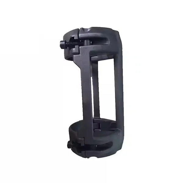


Cable Protector Clamp

Custom ESP Cable Protector Clamps: OEM Manufacturing FAQs
Can SIMIS manufacture ESP downhole cable protector clamps from our drawings?
Yes. SIMIS supports drawing-based OEM manufacturing of downhole cable protector clamps for electric submersible pump (ESP) systems, production tubing and associated control lines. Depending on the required alloy, clamp geometry and order quantity, production can involve precision investment casting, shell mold casting, CNC machining, heat treatment and protective finishing. We review the tubing interface, cable channels, fastening mechanism, service environment and inspection requirements before proposing a manufacturing route.
What is the difference between a cross-coupling protector and a mid-joint clamp?
A cross-coupling protector is designed to shield cables or control lines where they pass a tubing coupling, which is generally larger than the tubing body. A mid-joint clamp secures cables or lines along the tubing body between couplings. Their internal profiles, installed outside diameters and retention requirements may differ. The customer should specify the actual tubing, coupling and cable dimensions for the intended location.
Which materials can be used for downhole cable protection clamps?
Carbon steel, alloy steel and stainless steel are potential options, including certain duplex stainless alloys where specified. The selection depends on temperature, chloride concentration, carbon dioxide, hydrogen sulfide, fluid chemistry, mechanical loading and the customer's applicable standards. No stainless steel grade should be described as suitable for every sour or high-temperature well merely because it has good general corrosion resistance.
Can the cable grooves, tubing seats and bolt features be precision machined?
SIMIS supports CNC finishing of selected contact surfaces, mounting interfaces, bolt holes and other critical features according to the drawing. Some cable-channel geometry may be formed during casting, while dimensions requiring tighter control can receive secondary machining where practical. The finished profile must provide the specified cable clearance and retention without relying on excessive compression of the cable jacket.
What information is required for an ESP cable protector clamp quotation?
Please provide 2D drawings and available 3D models, tubing outside diameter, coupling dimensions, cable or flatpack cross-section, number of control lines, required clamp length, material grade, fastening details and estimated order quantity. Include the well temperature, fluid composition, hydrogen sulfide exposure where applicable, required installed envelope, inspection requirements and any qualified assembly or installation procedure.
Custom Downhole Cable Protector Clamps for ESP Completion Systems
An ESP cable protector clamp is a mechanical component used to support and protect the electrical power cable, control line, capillary tube or similar service line installed along the outside of production tubing. In electric submersible pump systems, these lines can be exposed to contact with tubing couplings, casing surfaces and other completion hardware during installation, operation or retrieval.
The clamp typically includes a shaped body that fits around the tubing or coupling, one or more channels for protected lines, and an attachment mechanism. Depending on the design, the body may use separate halves, hinged sections, bolted closures or another approved retention arrangement. The precise geometry must match the equipment rather than a generic nominal tubing description.
SIMIS provides custom cast steel and precision-machined components based on customer drawings. For downhole cable protectors, the manufacturing objective is to reproduce the approved clamping and clearance geometry with the specified material and inspection requirements. A dimensionally correct clamp is an important component, but final completion compatibility must be verified at the assembly level.

ESP Cable Protector Types and Installation Positions
A downhole cable protection system may use several protector designs along the same completion string. The required type depends on where the clamp is installed and the geometry of the equipment being protected. Cross-coupling protectors and mid-joint clamps have different functions and should not be treated as interchangeable.
| Protector Type | Main Function | Important Design Data |
|---|---|---|
| Cross-Coupling Protector | Shields cables and control lines at tubing coupling locations | Tubing OD, coupling OD and length, cable channels and running clearance |
| Mid-Joint Cable Clamp | Supports and retains lines along the tubing body | Tubing OD, line size, clamp closure and required grip |
| Motor Lead Extension Protector | Protects the specified motor lead extension near ESP equipment sections | Pump or motor envelope, lead configuration, transition geometry and attachment position |
| Multi-Line Protector | Accommodates combinations of electrical, hydraulic or instrument lines | Line arrangement, separation, channel dimensions and approved retention method |
The installed clamp must also be considered within the available annular clearance. Tubing size alone does not define this clearance: coupling dimensions, casing restrictions, the protected cable bundle and the maximum installed protector envelope are relevant. These parameters should be confirmed against the well completion design before tooling is approved.

Investment Casting and Other Manufacturing Processes
Precision casting can be suitable for cable protectors containing curved tubing seats, multiple cable channels, reinforcing ribs and integrated fastening features. The selected method must reproduce the required geometry while providing acceptable material and casting quality. The best manufacturing route depends on alloy, part size, complexity and production volume.
Investment casting for complex steel clamp bodies
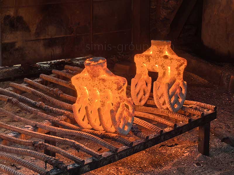
Lost-wax investment casting is often a practical route for detailed ESP cable protector bodies. The process can produce curved contact regions, cable passages, external ribs and fastening bosses in a near-net shape. It is particularly relevant where a selected stainless steel or alloy steel requires complex geometry with limited excess machining.
Tooling and foundry planning should address thin sections, internal corners, casting shrinkage, gate location and local soundness near loaded fastener areas. SIMIS can evaluate these factors through its precision investment casting capabilities. Investment casting does not eliminate dimensional variation or guarantee freedom from porosity.
Shell mold casting for selected steel designs
Shell mold casting may be considered for suitable clamp components with less complicated geometry or specific batch-production requirements. The decision depends on material compatibility, tooling, the achievable casting envelope and the machining needed for final fit. See SIMIS shell mold casting processes for related manufacturing options.
Machined and fabricated alternatives
Some protector designs may use formed steel or machined components rather than a fully cast body. These routes can be relevant for simpler channels, smaller quantities or customer-approved multi-piece structures. However, joints, formed sections and fastening details introduce their own dimensional and structural requirements. The approved clamp design—not a general preference for casting—should determine the manufacturing method.
| Manufacturing Route | Potential Application | Key Considerations |
|---|---|---|
| Investment Casting | Detailed steel bodies with multiple channels and integrated features | Wax tooling, section thickness, casting integrity and finish machining |
| Shell Mold Casting | Selected repeat-production clamp components | Tooling economics, size and dimensional repeatability |
| Steel Fabrication | Appropriate formed or assembled protector designs | Joint details, forming accuracy and final attachment geometry |
| CNC Machining | Critical contact surfaces, holes and fastening interfaces | Drawing datums, profile tolerances and surface condition |
Material Selection for Downhole Cable Protector Clamps
Downhole material selection requires consideration of both mechanical loading and environmental exposure. Temperature, chloride content, hydrogen sulfide, carbon dioxide, fluid chemistry and the expected service period may all influence corrosion and cracking risks. The customer should specify the required alloy grade and any applicable material qualification requirements.
Stainless steel and duplex stainless steel
Certain stainless steel grades may be specified for cable protector clamps where corrosion resistance is important. Austenitic and duplex stainless alloys have different combinations of strength, corrosion behavior and fabrication requirements. Duplex and super duplex grades should not be treated as universally suitable for all sour service environments. Their allowable conditions, heat treatment and metallurgical acceptance requirements must be checked against the specified grade and service conditions. SIMIS supports related custom stainless steel castings.
Carbon and low-alloy steel
Carbon steel can be considered where the engineering specification and exposure conditions permit. Low-alloy steel may provide other strength and heat-treatment options. However, hardness, strength level, environmental cracking susceptibility and coating strategy must be reviewed before selecting a particular grade. SIMIS can discuss cast carbon steel components and alloy steel castings according to the approved material specification.
Sour service and H2S-containing wells
For applications requiring sour-service material controls, the customer should identify the applicable ANSI/NACE MR0175/ISO 15156 requirements and the defined well environment. Suitability depends on the particular material, metallurgical condition and applicable environmental limits. Specifying stainless steel or applying a protective coating does not automatically establish compliance with these requirements.
| Material Category | Potential Benefit | What Must Be Verified |
|---|---|---|
| Carbon Steel | Practical manufacturing option for suitable specified environments | Material grade, hardness, corrosion exposure and applicable sour-service restrictions |
| Alloy Steel | Project-specific strength and heat-treatment options | Heat-treated condition, mechanical properties and environmental cracking risk |
| Austenitic Stainless Steel | Selected corrosion-resistant alloy options | Chlorides, temperature, grade-specific limits and casting condition |
| Duplex or Super Duplex Stainless Steel | Specified strength and corrosion-resistance combinations | Exact alloy, phase balance, heat treatment and permitted well conditions |
No material should be described as providing permanent resistance to all forms of corrosion, sulfide stress cracking or stress corrosion cracking. The final material specification and acceptance criteria remain the responsibility of the equipment designer and purchaser.

Critical Clamp Geometry: Tubing Fit, Cable Channels and Running Clearance
The functional geometry of an ESP cable protector clamp must accommodate several components at once: the tubing or coupling, one or more cables or lines, the closure mechanism and the available space inside the completion. Controlling a single inside diameter is therefore insufficient to establish an acceptable assembly.
Tubing and coupling contact profiles
The inner clamp profile should match the approved tubing or coupling envelope. Important dimensions may include the tubing outside diameter, coupling diameter, coupling length, clamp contact surfaces and closure gap. Contact should be evaluated for both assembly retention and the risk of creating excessive localized stresses on the tubing or protector body.
Flat, round and bundled cable channels
Electrical power cables, flatpacks, hydraulic control lines and capillary tubes can require different channel profiles. Groove width, depth, edge radius and internal clearance should reflect the actual protected item, including its jacket or encapsulation. Sharp corners and unsuitable localized contact may damage cable insulation or tubing. Where several lines share one protector, their arrangement and separation should be identified on the drawing.
Installed outside diameter and downhole restrictions
The assembled protector must fit within the relevant completion restrictions. The maximum running outside diameter is influenced by the clamp body, hinge, fastener heads, cable position and any protruding features. Available clearance should be compared with the actual casing or wellbore restrictions and other installed equipment. The component manufacturer should work from the approved envelope rather than assume that every protector for a given tubing size fits every well.
Assembly gap and manufacturing tolerance stack-up
Casting variation, machining tolerances, tubing dimensions, cable dimensions and fastener geometry can influence the final closure condition. The drawing should define the critical dimensions and, where appropriate, an assembled clearance or functional gauge. A visually closed clamp is not proof that the correct cable-retention force has been achieved.
Precision CNC Machining and Fastening Features
Investment casting can produce detailed near-net geometry, but selected functional surfaces may still require machining. SIMIS supports CNC machining of steel castings for critical fit features defined on the customer's drawing.
Bolt holes, hinge pins and threaded interfaces
The closure system may use threaded fasteners, hinge pins or a proprietary locking arrangement. Hole position, pin fit, thread quality and local material thickness can influence assembly. The specified connection method should also allow suitable installation access while avoiding sharp projections that could interfere with running clearance.
Cable-contact surface finish
Cable-contact regions should be checked for the specified contour, edge radius, burrs and casting flash. A smooth-looking casting is not necessarily suitable for every jacket material. Where a particular surface finish is required, it should be stated on the drawing together with any protective insert or interface component specified by the customer.
Functional fit checks after machining
A representative tubing and cable gauge or customer-approved assembly fixture may be used to check critical fit features. Final acceptance should use defined tolerances rather than a generic promise of perfect fit. If a field-installed fastening procedure specifies tightening torque or a locking method, the production design must be compatible with that procedure.

Clamping Force, Cable Protection and Structural Integrity
The purpose of a downhole cable protector is not simply to apply the greatest possible clamping force. The connection should retain the protected lines and maintain the specified position without damaging cable jackets, collapsing small tubes or overstressing the protector body. The allowable contact and retention conditions must be defined by the equipment designer.
Retention without excessive cable compression
Cable jackets, encapsulated control lines and metal capillaries respond differently to contact pressure. Groove shape and closure travel should be designed around the approved line configuration. Excessive localized force may damage insulation or deform tubing, while insufficient retention may allow unwanted movement. Both conditions need consideration during component and assembly validation.
Hinge, bolt and casting load paths
Fastening loads are transmitted through hinge areas, clamp arms, threaded bosses and surrounding cast sections. Fillet radii, wall thickness and local casting integrity can be important near these features. The required preload, bolt grade, assembly torque and any locking arrangement should be specified as part of the approved clamp design.
Handling, impact and repeated downhole exposure
Cable protectors may encounter mechanical contact during completion installation or retrieval, together with environmental exposure during service. The relevant impact, bending, vibration or fatigue requirements depend on the actual deployment conditions. A project-specific test plan may be appropriate, but no fixed service-life or anti-vibration guarantee should be inferred from investment casting alone.
Heat Treatment and Corrosion Protection for Downhole Service
Certain cast steel grades require a specified heat-treated condition to develop their mechanical properties or appropriate microstructure. The selected treatment depends on the alloy, casting section and applicable specification. Stainless and duplex alloys may have particular solution-treatment and metallurgical requirements, while carbon and low-alloy steels can require different processing schedules. SIMIS can review relevant parts heat treatment requirements for approved material grades.
Corrosion mechanisms and environmental limitations
Chloride-related corrosion, pitting, stress corrosion cracking and sulfide stress cracking are distinct concerns. A material suitable for one exposure condition may not be acceptable under another. The relevant temperature, pressure, aqueous chemistry and sour-service classification should be provided by the buyer so the required grade and verification program can be identified.
Protective coatings and finishing
Cleaning, passivation or other alloy-appropriate finishing may be specified for selected stainless components. Carbon steel parts may use project-approved coatings in suitable environments. However, a coating can be damaged during installation, and it does not automatically qualify an otherwise unsuitable alloy for sour service. SIMIS can discuss surface treatment options based on the customer's specification.

Quality Inspection for ESP Cable Protector Clamps
Quality inspection should address the specified material, casting integrity, functional dimensions and fastener interfaces. Where the clamp is used in demanding downhole service, the buyer may also require additional metallurgical examination, corrosion-related qualification or assembly-level testing. The scope should be established before manufacturing.
| Inspection Item | Project-Defined Verification |
|---|---|
| Material Grade | Chemical composition, mechanical properties and heat-treated condition |
| Metallurgical Condition | Hardness, microstructure or alloy-specific examinations where specified |
| Tubing and Cable Fit | Contact geometry, channel dimensions, closure gap and functional gauges |
| Running Envelope | Overall assembled dimensions, projections and required clearance |
| Fastening Features | Thread dimensions, hinge alignment and approved attachment fit |
| Casting Integrity | Visual examination and specified NDT with defined acceptance criteria |
| Assembly Performance | Retention, closure, torque or other functional tests where agreed |
| Documentation | Material reports, dimensional results, lot identification and agreed traceability |
Dimensional inspection and first-article verification
CMM measurement, conventional gauges and purpose-designed assembly fixtures may be used to inspect critical clamp geometry. First-article verification can help confirm that the finished tubing seat, cable channel and fastening arrangement correspond to the approved model. Any functional check should use defined dimensions and acceptance criteria.
Non-destructive examination of cast steel
Magnetic-particle inspection may be suitable for selected ferromagnetic steels, while liquid-penetrant examination can be relevant for surface-breaking indications on appropriate materials. Radiography or other examinations may be required for specific casting regions. Each method has limitations and must be specified with an appropriate procedure, coverage and acceptance standard. Passing an inspection does not establish a completely defect-free casting.
Functional retention and cable-damage assessment
When the customer requires an assembly-level test, the plan should define the tubing and cable specimens, fastening procedure, applied loads, test duration and acceptance conditions. The test may consider retention and visible cable damage under specified conditions. A component-level test cannot automatically establish performance throughout every possible downhole temperature, fluid chemistry or installation event.
SIMIS can review inspection methods, documentation and lot traceability through its quality control processes. Required certifications or test reports should be identified in the purchase specification rather than assumed for every order.
Applications in Oil, Gas and Geothermal Completion Systems
Oil and gas wells using electric submersible pumps
ESP completion strings use power cables and associated accessories along the production tubing and pump equipment. Cable protectors may be positioned at specified coupling locations and other points identified by the completion designer. The approved design must account for tubing, coupling, cable and casing dimensions, as well as the deployment environment.
Control lines, instrumentation and chemical injection systems
Other completion systems may include hydraulic control lines, chemical injection capillaries, tubing-encapsulated conductors, fiber-optic lines and instrumentation cables. These components can require different protective channel shapes and retention arrangements. A clamp designed for one flat ESP power cable should not automatically be used for a different line configuration.
Geothermal well equipment
Geothermal systems may incorporate protected power, measurement or control lines in high-temperature environments. Material suitability depends on actual fluid chemistry, temperature and equipment geometry. A particular corrosion-resistant alloy should only be selected after reviewing these conditions and the applicable engineering requirements.
Other specialized downhole and underground applications
Cable protection concepts may also be relevant to other energy and underground equipment. However, a clamp designed for production tubing is not automatically suitable for a mine-shaft cable or a different support structure. Mounting geometry, applicable hazards and qualification requirements must be reviewed for each use. SIMIS supports related energy and power equipment metal parts based on customer drawings.
Request a Quote for Custom ESP Cable Protector Clamps
SIMIS supports OEM manufacturing of precision cast steel cable protector clamps for ESP systems and related downhole equipment. Our manufacturing review can address casting feasibility, alloy specification, functional machining, fastening features, heat treatment, surface finishing and the required component inspection plan.
For a detailed RFQ, please provide: 2D technical drawings and STEP or other available 3D models; cross-coupling, mid-joint or other protector type; tubing outside diameter; coupling dimensions; cable and control-line profiles; maximum permitted running diameter; clamp length and fastening arrangement; required steel grade; well temperature and fluid conditions; applicable sour-service requirements; desired inspection documents; and anticipated batch and annual quantities.
If the project requires specific retention tests, environmental qualification, corrosion testing or a controlled installation procedure, please include those requirements with the inquiry. Material substitutions, changes to cable-contact geometry and modifications to critical fasteners should be approved by the customer's responsible engineering team before manufacturing.
Send your custom ESP downhole cable protector clamp drawings and purchasing specifications to info@simis-group.com for a manufacturing feasibility review and quotation.