Custom Floor Drain Base Manufacturer
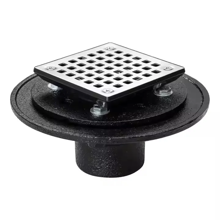


Floor Drain Base

Custom Floor Drain Base Manufacturing FAQs
Can SIMIS manufacture cast iron floor drain bases from our drawings?
Yes. SIMIS supports drawing-based OEM production of metal floor drain bases, drain bodies and drainage housings. We review 2D drawings and available 3D files to determine the proposed casting method, material, mold and core design, machining allowances and inspection requirements. Components are made for the customer's own drainage assembly or construction project rather than supplied as universal off-the-shelf replacements.
Which casting process is suitable for a custom floor drain body?
Sand casting is a common option for gray iron and ductile iron drain bodies, especially where outlets, mounting flanges or internal cavities are required. Shell mold casting may suit selected smaller parts or repeat orders, while lost foam casting can be evaluated for particular integrated geometries. The final choice depends on dimensions, wall thickness, production quantity, material and the required finished interfaces.
Which dimensions are most important for sealing and installation?
The outlet connection, pipe interface, gasket or sealing seat, top-frame location, flange face and bolt-hole pattern should be clearly defined. Grate seating dimensions and any trap or cleanout features must match the mating parts. We can evaluate machining of functional faces and openings, but leak resistance and fit depend on the entire assembly, its seals, installation and the agreed test conditions.
Should a floor drain base be gray cast iron or ductile iron?
Gray cast iron may suit many appropriately designed drainage bodies, while ductile iron can be considered where the specified load case calls for different strength or ductility. Corrosion exposure, coating, section thickness, connection type and application standards also influence selection. Material changes need the customer's approval and cannot be inferred from a generic load-class claim.
What information is required for an OEM floor drain base quotation?
Please provide drawings or CAD models, required material grade, overall dimensions, outlet size and connection type, critical tolerances, estimated quantity and any specified coating or inspection documents. If water-tightness testing, a grate load class or a floor-drain standard applies, include the exact requirements and clarify whether the order covers only the metal base or a complete assembled drain.
OEM Cast Iron Floor Drain Bases Made to Customer Drawings
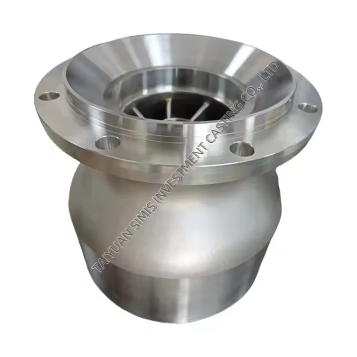
A floor drain base forms the supporting body or outlet interface within a drainage assembly. Depending on the design, it may locate a grate frame, connect to a waste pipe, support a removable strainer or incorporate a specified sump, flange or water-seal feature. Unlike a finished floor-drain system, an individual cast base cannot establish drainage capacity, water-tightness or installation performance on its own.
SIMIS manufactures custom metal components from customer drawings, with production planning centered on casting geometry and the functional surfaces that must be finished after casting. For OEM drainage programs, this means reviewing the pipe connection, mating seals, grate seat and installation conditions before tooling is approved. The resulting manufacturing route may combine a cast iron body with selective CNC machining, cleaning and customer-specified protective finishing.

Engineering Details That Matter for Custom Drain Base Castings
Good floor drain manufacturing starts with clear interfaces, not just the outside dimensions of a casting. A change in outlet orientation, gasket groove or frame height can affect assembly fit even when the overall drain body looks similar. We therefore recommend identifying functional dimensions and inspection datums on the drawing before production begins.
| Design feature | What the OEM drawing should define | Manufacturing consideration |
|---|---|---|
| Outlet hub / pipe connection | Nominal and actual connection dimensions, thread or spigot type, mating pipe and installation method | Core location, machining allowance, bore or thread finish |
| Grate seat / top frame | Seat opening, recess depth, mounting height and mating component dimensions | Flatness, seating alignment and selected machined surfaces |
| Flange and gasket interface | Gasket seat, groove dimensions, bolt pattern and sealing face requirements | Surface finish, hole position and distortion control |
| Internal sump or water-seal geometry | Channel shape, depth, minimum openings and service/cleanout access | Core design, wall transitions, cleaning and inspection access |
| Base supports and wall sections | Local loads, ribs, wall thickness, bearing areas and mounting conditions | Casting soundness, section transitions and as-cast dimensional allowance |
Casting draft, shrinkage allowances and suitable core supports should be assessed together with the finished machining datums. Sharp section changes and isolated heavy bosses can complicate feeding or create local casting-quality risks. Where a finished face must align with a pipe outlet or a grate, its datum relationship should be explicit rather than relying on a general dimensional tolerance for the entire casting.
Floor Drain Base Manufacturing Processes
Sand Casting for Cast Iron Drain Bodies
Sand casting is a flexible process for drain bases with substantial walls, curved cavities and non-standard outlet configurations. Gray iron or ductile iron castings can be made with a sand core where the design requires an internal passage. Feasibility depends on core access, minimum wall thickness, pattern layout, batch size and the amount of finish machining needed. It is often a practical choice for OEM cast iron drain bodies with customized dimensions.
Shell Mold Casting for Selected Repeat-Production Parts
Shell mold casting may be evaluated for suitable smaller or medium-sized drain components where consistent molded detail and production repeatability are important. The benefits should be weighed against metal-pattern investment, part size, section geometry and the actual tolerance requirements. It does not remove the need to machine functional gasket faces or precision pipe connections when specified.
Lost Foam Casting for Particular Integrated Shapes
Lost foam casting is another option for selected drain-body designs containing integrated ribs, recesses or complex external geometry. Foam pattern accuracy, coating, gas control and metal solidification must be reviewed for each part. It is an alternative manufacturing route, not a universal solution for all internal drain passages or pressure-/leak-related requirements.
CNC Machining for Pipe Outlets and Mating Faces
After casting, CNC machining can be applied to customer-designated surfaces such as outlet bores, threaded connections, flange faces, grate seats, gasket grooves and bolt-hole patterns. Only those areas requiring functional accuracy generally need to be machined. The final tolerance plan should distinguish as-cast dimensions from machined dimensions, and each drawing should establish its own achievable requirements.

Gray Iron, Ductile Iron and Other Drain Base Materials
Material selection must reflect the drain's intended environment and geometry. Gray cast iron is used in many drainage castings because it can form complex shapes and is relatively straightforward to machine. Ductile iron may be appropriate for designs needing different elongation and mechanical response. Specific material standards and grades should be provided by the buyer or confirmed during engineering review.
| Material option | When it may be considered | Important qualification |
|---|---|---|
| Gray cast iron | General building and industrial drain-base castings with suitable design and load cases | Confirm grade, section thickness, corrosion exposure and any coating requirements |
| Ductile iron | Drain bodies requiring different strength or ductility characteristics | Specify the grade, mechanical acceptance and relevant loading conditions |
| Corrosion-resistant iron or other alloys | Specified industrial wastewater or more aggressive fluid environments | Check the actual chemistry, temperature and compatibility with the medium |
| Aluminum alloy | Approved lightweight or specialist drain-body configurations | Verify alloy, casting route, mechanical loads and environmental suitability |
For broader information about ferrous casting options, see our custom gray iron parts page. Uncoated cast iron should not be described as inherently immune to corrosion. Paint, epoxy or another specified protective finish may be required depending on service exposure; compatibility with wastewater and the installation environment must be assessed by the OEM.
Inspection Planning, Drainage Standards and Assembly Responsibilities
A custom metal floor drain base may need material verification, casting-surface checks and dimensional inspection of its mounting and connection features. The exact scope is determined by the customer's drawings and purchase specification. For critical castings, the agreed plan may additionally define non-destructive examination, sample testing or traceability records.
Critical dimensions: outlet diameter, flange face, seal recess, bolt pattern, grate seat and drawing datums.
Material requirements: specified casting grade and any required chemical, mechanical or hardness records.
Casting condition: defined acceptance criteria for relevant visual or internal discontinuities.
Leak or pressure tests: a written procedure and acceptance limit if component-level testing is required.
Finish and documentation: agreed surface protection, inspection results and traceability where specified.
For building floor drains, a customer may identify requirements from ASME A112.6.3/CSA B79.3 or the relevant EN 1253 series, depending on jurisdiction and product configuration. These concern drain products and their performance in defined scopes; manufacturing one cast base does not establish compliance for the completed drain, grate, seals, pipe joints or installation. The applicable edition and assembly-level testing responsibility should be confirmed before production.
Similarly, a specified top-load classification is not automatically proven by changing from gray iron to ductile iron. The load path includes the grate or cover, its frame, the supporting casting and the surrounding floor structure. Claims for a completed installation require the appropriate design analysis and validation by the responsible product or system supplier.
Applications of Custom Floor Drain Castings
Commercial Buildings and General Facilities
Custom drain bodies can be specified for building washrooms, utility rooms, service corridors and similar drainage locations. Important interfaces include grate dimensions, floor build-up height, outlet connection and access for cleaning. The required water seal and odor-control function, where applicable, must be designed as part of the complete drain assembly.
Industrial Floors and Washdown Areas
Manufacturing facilities may use drain-body designs with specialized outlet orientation, heavier seating features or corrosion-related material requirements. Wastewater composition, cleaning fluids, operating temperature and floor loads should be identified by the buyer to support suitable material and finish selection.
Municipal and Infrastructure Applications
Municipal drainage castings may require larger or nonstandard geometries and durable interfaces with surrounding infrastructure. For related application areas, explore our municipal engineering metal components page. The designer should distinguish an indoor floor drain from a roadway or stormwater inlet, as the relevant product standards, load cases and assembled systems may differ.
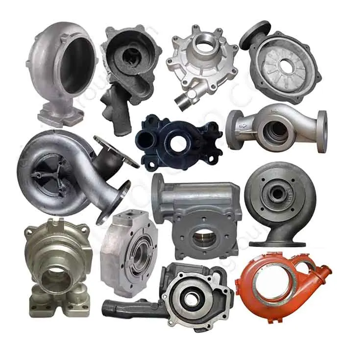
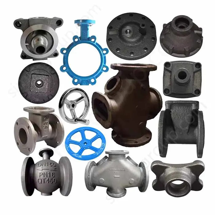
Other drawing-based components used in fluid-handling systems include custom pump housings and custom valve parts, although their pressure and sealing specifications are evaluated separately from floor-drain bodies.
Request a Quote for Custom Floor Drain Bases
SIMIS supports OEM purchasing teams that need a floor drain base or drainage housing made to a specific design, rather than a retail catalog drain. We can review casting feasibility, tooling, core design, finishing requirements and critical machining features based on the supplied drawings and planned order quantities.
Drawings: 2D PDF/DWG and available STEP or other CAD files, showing the finished part and mating interfaces.
Material: specified gray iron, ductile iron or other approved grade, plus applicable standard and coating requirements.
Interfaces: outlet geometry, pipe size and connection, grate seat, gasket location, bolt holes, mounting height and critical tolerances.
Project conditions: exposure, temperatures, expected loads, applicable product standards and any testing or inspection documents.
Purchasing details: sample quantity, production batch, annual forecast, delivery destination and other quotation requirements.

Send your floor drain base drawings and RFQ details to info@simis-group.com, or use our contact page. We can evaluate an appropriate manufacturing route and quote the custom metal component against your approved specifications.