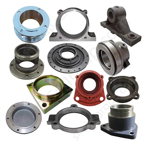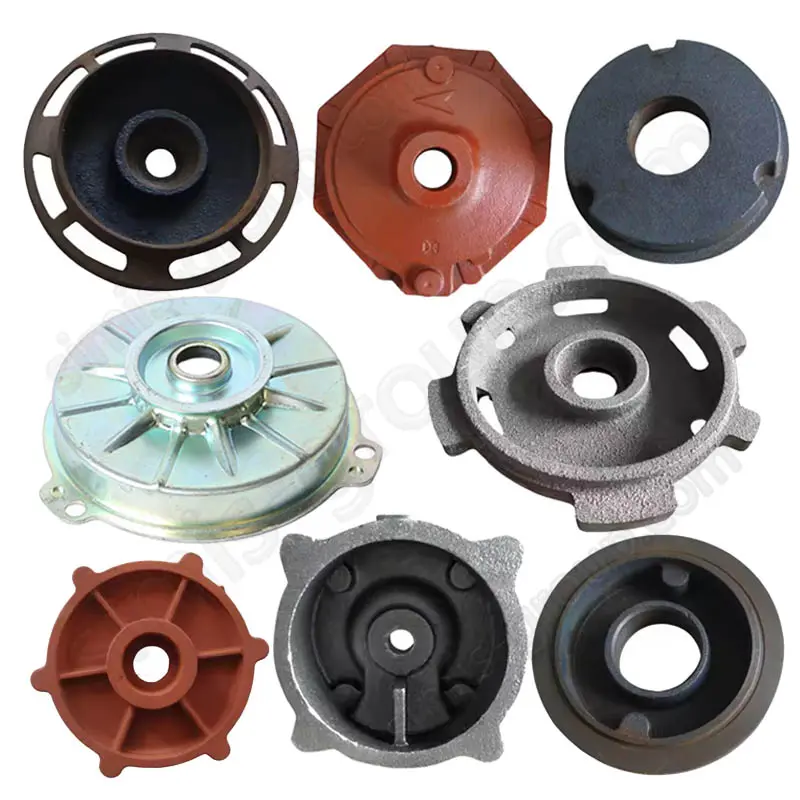
Custom Lathe Chuck Manufacturer
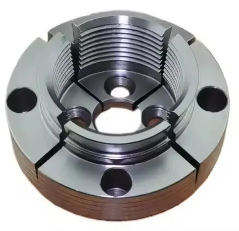


Lathe Chuck

Custom Lathe Chuck Manufacturing FAQs
Can SIMIS manufacture custom lathe chuck bodies and parts from our drawings?
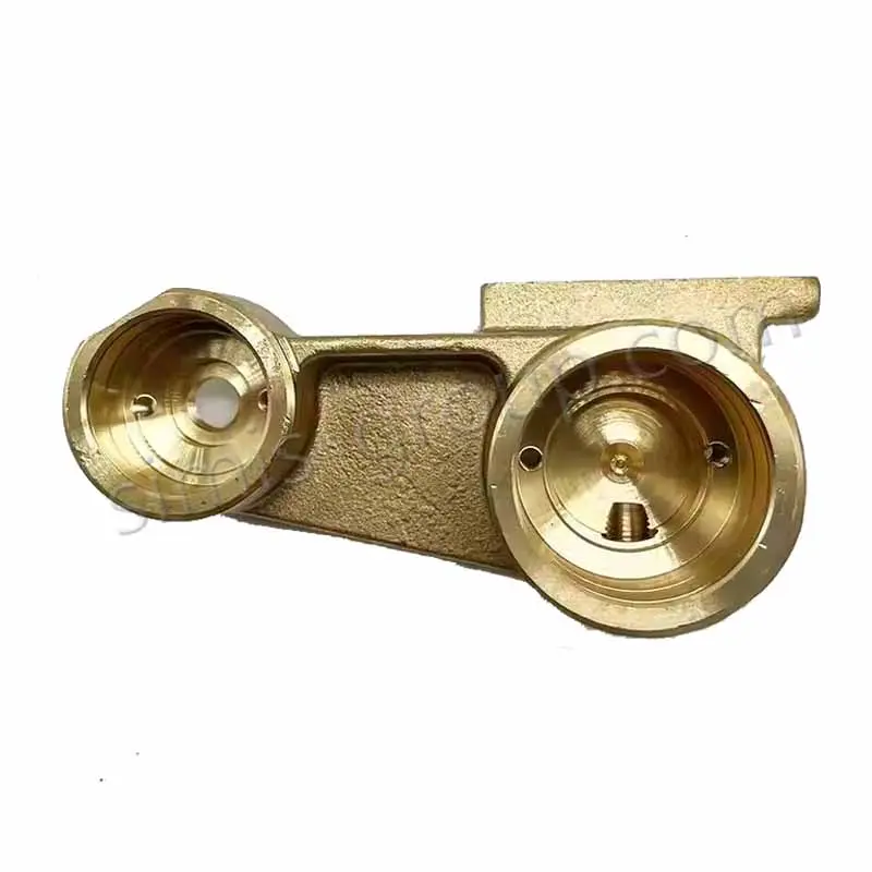
Yes. SIMIS supports OEM manufacturing of metal chuck bodies, backing plates, jaw blanks and other drawing-defined workholding components. We review the required material, geometry, quantity and functional interfaces before selecting casting, forging and/or CNC machining. Whether the order covers individual machined components or a larger assembly must be agreed during quotation; we do not assume every customer needs a complete ready-to-operate chuck.
Which process is suitable for a lathe chuck body: casting or forging?
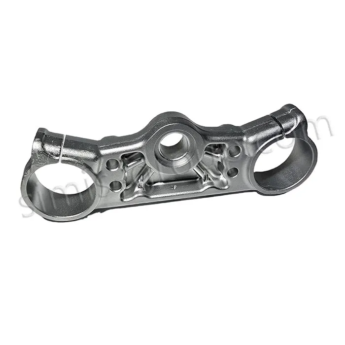
Sand-cast iron can be a practical starting point for some chuck bodies with circular sections, internal pockets and substantial walls. Ductile iron or steel may be considered where the specified loading and design require different mechanical properties. Forged steel blanks can suit selected highly loaded components, while solid bar or plate machining is often economical for small quantities and comparatively simple shapes. Final process selection follows the drawing, expected production volume and specified acceptance requirements.
What is the difference between three-jaw and four-jaw lathe chuck components?
A conventional self-centering three-jaw scroll chuck moves its jaws together through a scroll mechanism; an independent four-jaw chuck lets each jaw move separately. These mechanisms require different jaw slots, driving details, tolerances and part interfaces. The number of jaws alone does not define gripping force, centering accuracy or permissible rotational speed. Please provide the original chuck design or mating component drawings rather than using a generic jaw arrangement as the manufacturing specification.
How are chuck register accuracy, jaw guides and runout controlled?
The mounting register, spindle-side locating face, chuck body bore and jaw-guide geometry must be controlled relative to the specified datums. CNC turning, milling, boring and other finishing operations can be planned for those features. Radial runout measured on the body, mounting interface and gripped test workpiece can give different results, so the drawing should specify each inspection point and limit. We cannot assign a single guaranteed total indicated runout (TIR) to every custom chuck design.
What information is required for an OEM lathe chuck quotation?
Please send 2D drawings and, where available, 3D CAD models of the component or assembly. Specify chuck diameter, spindle mounting standard or complete interface dimensions, through-bore, material, jaw configuration, critical fits and tolerances, quantities and intended manual or powered operation. Include any specified maximum speed, gripping-force requirements, test method and inspection documentation. We will review manufacturability and confirm the proposed supply scope.
Drawing-Based OEM Manufacturing for Lathe Chuck Components
A lathe chuck secures a workpiece while a spindle rotates during turning or other machining operations. The chuck body supports the jaw system and connects to the spindle, but accurate workholding depends on the complete mechanical design: the body, locating faces, jaws, drive mechanism, mounting fasteners and machine spindle must work together.
SIMIS focuses on custom metal manufacturing rather than retail listings for universal replacement chucks. For machine-tool OEMs and workholding equipment manufacturers, the production plan can combine a cast or forged blank with precision machining of defined mating surfaces. That distinction is especially important for chuck bodies and jaw carriers, where an attractive casting is not the same as an assembled, qualified workholding device.

Common Custom Lathe Chuck Parts and Their Critical Features
Different components require different manufacturing methods. The table below describes representative parts that may be evaluated against customer drawings; no process is automatically required for every design.
| Component / feature | Possible manufacturing route | Engineering considerations |
|---|---|---|
| Chuck body or housing | Cast iron or specified steel blank, followed by turning and milling | Spindle register, rear mounting face, jaw-guide geometry, concentric features, section thickness |
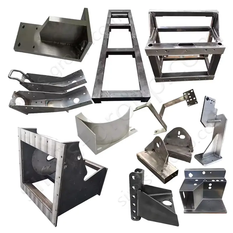
| Mounting backplate / adapter plate | Cast iron, steel plate or other approved stock; CNC machining | Spindle nose connection, bolt-hole circle, pilot diameter, seating faces, fastener engagement |
| Top jaws or special gripping jaws | Specified steel stock or forged blank; profile machining | Gripping geometry, serrations, mounting slots and fastener layout, workpiece contact |
| Master jaw / slide component | Drawing-approved steel; machining and any specified finishing | Guide fit, engagement geometry, sliding clearance and interchangeability |
| Scroll or actuating element | Specified steel blank with precision-machined drive geometry | Tooth / scroll geometry, mating engagement, assembly clearance, wear requirements |
| Flanges, covers and retaining rings | Casting, forging or stock machining as suitable | Assembly location, bolt patterns, access and clearances |
For customers purchasing a matched group of parts, please identify the revision level and datum scheme shared between the chuck body and mating components. In a self-centering scroll chuck, the angular relationship, jaw numbering and driving geometry may affect assembly; a generic replacement jaw drawing is often insufficient.

Casting, Forging and CNC Machining Options for Custom Chuck Parts
Sand Casting for Selected Chuck Bodies and Circular Housings
Sand casting can be evaluated for relatively substantial cast iron chuck bodies, especially when the design includes recesses, stepped sections or features that would otherwise require extensive stock removal. Pattern draft, local wall thickness, shrinkage allowances and machining stock must be addressed at the tooling stage. Critical spindle and jaw interfaces are normally specified as finished features rather than left entirely as-cast.
Shell Mold Casting for Suitable Repeat-Production Components
For selected chuck-body or smaller housing geometries, shell mold casting may offer useful repeatability when production quantities justify its pattern tooling. Casting route selection must still consider material, minimum sections, internal complexity and post-casting machining. A more repeatable casting does not remove the need to verify the functional locating and sliding features.
Forging for High-Load Steel Chuck Components
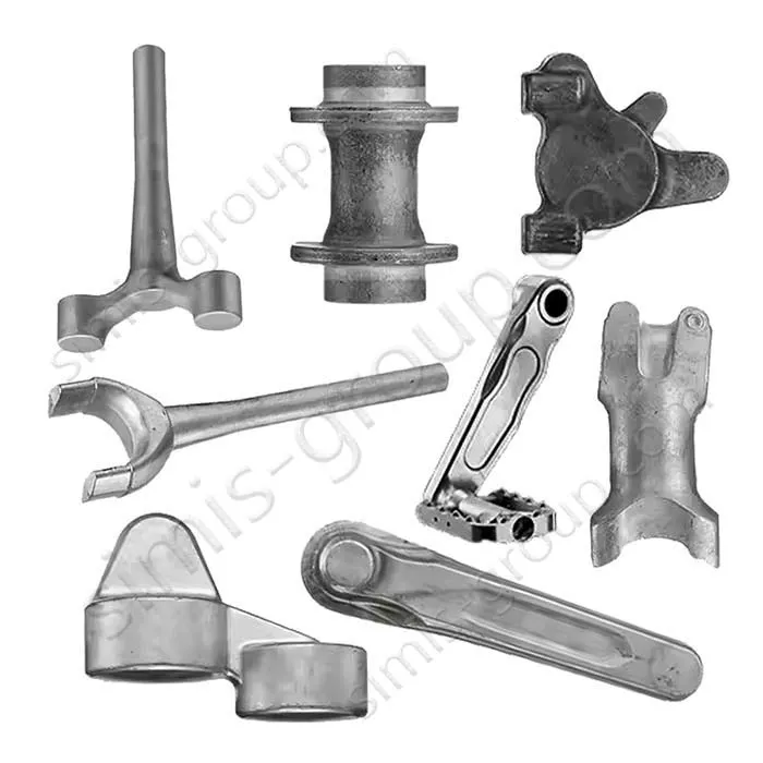
Closed-die forging may be considered for steel jaw blanks and other repeated, load-carrying shapes when part geometry and quantity support a die. Open-die forging can be evaluated for larger or simpler steel blanks. The choice should be based on material condition, mechanical requirements, machining allowance and total production cost; forging is not inherently the preferred route for every chuck body.
CNC Turning, Milling and Boring for Precision Interfaces
CNC machining is central to many custom workholding components, particularly the chuck-body pilot, register, rear face, central bore, jaw slots, mounting holes and adapter-plate features. Turning can establish related circular datums; milling and boring can then produce jaw guides, attachment holes and mating locations. Grinding or other finishing may be specified for selected features when the drawing and assembly requirements justify it—not as a mandatory operation on every part.

Selecting Cast Iron and Steel for Lathe Chuck Parts
Material selection is part-specific. A chuck body and a gripping jaw may use different alloys because their geometry, contact conditions and stress paths differ. Customer-provided grades and applicable standards take priority over generic material advice.
| Material option | Typical reason to evaluate | Important limitations or requirements |
|---|---|---|
| Gray cast iron | Castable housing geometry, damping characteristics, machinability | Brittle behavior must be considered where impact or tensile loads are significant; verify the design load case |
| Ductile cast iron | A cast body requiring different strength and ductility from gray iron | Grade, casting soundness and mechanical-property evidence need to follow the drawing |
| Carbon or alloy steel | Jaws, adapters, mounting components or load-carrying parts | Material condition, wear requirements, toughness and final dimensions must be specified |
| Cast steel | Certain complex cast structures where the design calls for steel properties | Solidification, soundness, machining and qualification are project-dependent |
Grades such as FC250, ASTM A48 gray iron, ASTM A536 ductile iron, 45 steel or 42CrMo/4140 may appear in customer drawings, but they are not universally interchangeable. Equivalent-material proposals require a review of the governing standard, chemical and mechanical requirements, dimensions and approved substitutions. For material-specific machining and casting questions, our industrial machinery metal parts category provides broader application context.
Critical Dimensions for Lathe Chuck Bodies and Jaw Interfaces
Chuck manufacturing becomes more predictable when the drawings separate functional surfaces from noncritical external geometry. The following items deserve explicit definition on the 2D drawing or assembly model.
Spindle mounting interface: spindle-nose standard or complete mounting dimensions, pilot/register diameter, face location, bolt pattern and mating fasteners.
Chuck body reference datums: bore and rear face relationship, concentricity or runout limits measured at named surfaces.
Jaw guide geometry: guide width and depth, orientation, parallelism, sliding clearance and wear/contact surfaces.
Jaw engagement: serrations, threads, locating slots, attachment holes and mating-jaw identification as applicable.
Central through-bore: clearance for stock, actuating components or machine-spindle interfaces as required.
Speed and loading information: operating range and customer-defined load cases that could affect the material, geometry and acceptance tests.
Dimensional controls on individual parts do not automatically establish the assembled chuck's maximum permissible speed, clamping force or actual workpiece runout. Those properties depend on assembly configuration, gripping diameter, jaw mass, actuation and test setup. Any performance rating should be supplied or approved by the responsible chuck OEM and verified using a defined qualification procedure.
Inspection Planning for OEM Chuck Castings and Machined Parts
The required checks should be agreed during drawing review, with inspection effort matched to the component's function. A typical project plan may cover:
Material traceability: chemical composition and mechanical property evidence where specified.
Casting examination: visual condition and customer-specified internal or surface discontinuity checks.
Dimensional verification: diameter, face position, true position of holes, guide geometry, flatness and applicable runout measurements.
Fit checks: gauges or mating-part trials for chuck pilots, jaw guides, fasteners and interfaces where agreed.
Assembly-level verification: gripping-force, runout or speed testing only if the supply scope includes an approved assembled chuck and the required test method and equipment have been agreed.
In machine-tool applications, workholding is safety-critical. The customer remains responsible for validating the complete chuck and machine setup against the intended operating conditions. A machined component inspection report cannot replace a complete assembly test, safe-use instructions or operating-speed approval.
Applications for Custom Lathe Chuck and Workholding Components
Drawing-based chuck bodies, jaws and backplates can be relevant to machine-tool builders, turning-center OEMs, workholding equipment suppliers and manufacturers of special production fixtures. Examples include chuck bodies for general metal turning, special jaws for irregular workpieces, adapter plates for specified spindle configurations, and replacement components manufactured under an OEM-approved design.
For related machinery components, SIMIS also supports drawing-based manufacture of support shafts and drive shafts. These products involve different engineering requirements from chuck components, but they may appear in the same machine-tool or transmission equipment program. The exact assembly responsibilities should be stated in the purchase specification.
Request a Custom Lathe Chuck Parts Quotation from SIMIS
To prepare a useful OEM quotation, please include the component drawings or assembly references, expected quantities, material and material condition, required inspection records and delivery expectations. Mark all critical datums, fits and jaw/spindle interfaces on the drawings. If you need a chuck body only, specify that clearly; if you need multiple mating components, include their associated assembly drawings and inspection requirements.
Drawings: 2D PDF or DWG drawings and available 3D STEP/IGES models.
Configuration: three-jaw, four-jaw, other workholding arrangement, manual/power actuation and component scope.
Key dimensions: chuck diameter, mounting register, through-bore, jaw stroke/guide and bolt pattern.
Materials and tolerances: alloy grade, required condition, important datums, fits and finish on specified surfaces.
Application and commercial details: operating loads/speed information, testing scope, annual volume and target batch quantity.
Please contact SIMIS or email info@simis-group.com with your RFQ. We can review an appropriate casting, forging and machining route for the component design you provide.