Custom Bearing Seat Manufacturer
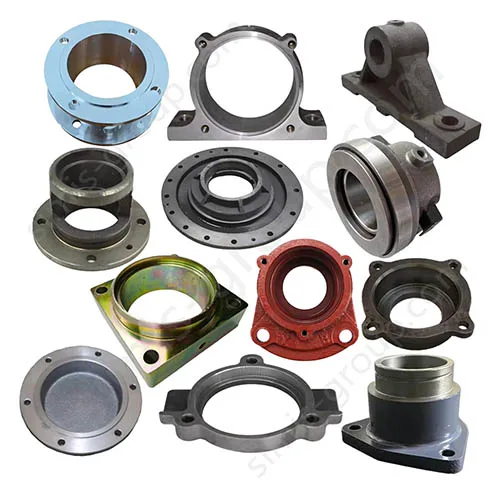


Bearing Seat

Custom Bearing Seat Manufacturing FAQs
Can SIMIS manufacture bearing seats and housings from our drawings?
Yes. SIMIS provides drawing-based OEM manufacturing for custom metal bearing seats, split bearing housings, bearing supports and mounting blocks. We review your 2D drawings or 3D models, bearing dimensions, material specification, loads and order volume to evaluate a suitable casting, machining or combined production route. Each quotation is based on the individual design rather than an off-the-shelf catalog size.
How do you control bearing bore fit, alignment and mounting accuracy?
The required bearing fit starts with the drawing: bore diameter and tolerance, roundness, coaxiality, datum references, shoulder location and mounting-face geometry. Critical bearing interfaces are normally finish-machined after the blank is produced. Inspection methods and acceptance limits are defined against the customer's drawing, the selected bearing arrangement and the agreed inspection plan.
Should a custom bearing seat be made from cast iron, steel or aluminum?
That depends on load direction, shock, stiffness, vibration, operating temperature, weight and corrosion exposure. Gray cast iron can suit rigid, vibration-damping supports; ductile iron may be appropriate where toughness matters; steel may be evaluated for severe loading or welded designs; and aluminum alloys can reduce weight. SIMIS reviews the specified grade and part geometry before recommending a manufacturing approach.
What do you need to quote custom bearing housing production?
Please send the 2D drawing and/or 3D CAD model, bearing type and size, material grade, critical fits and geometric tolerances, surface treatment, quantity per order, expected annual demand and inspection requirements. If available, include mating-part drawings and operating conditions so that machinability, tooling and inspection access can be assessed before quotation.
OEM Custom Bearing Seats and Housings Made to Your Drawings
A bearing seat is more than a metal support around a bearing. It establishes the position of a rotating shaft, transfers radial and sometimes axial forces into the machine frame, and holds the bearing assembly in the intended alignment. For an OEM buyer, the real manufacturing questions are whether the housing has sufficient rigidity, whether the bore and mounting surfaces can be machined to specification, and whether those features remain stable during assembly and service.
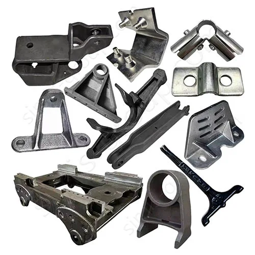
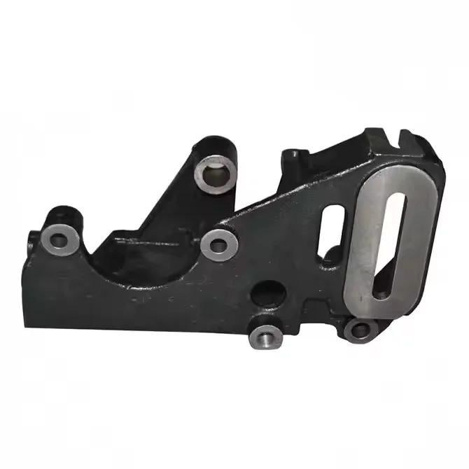
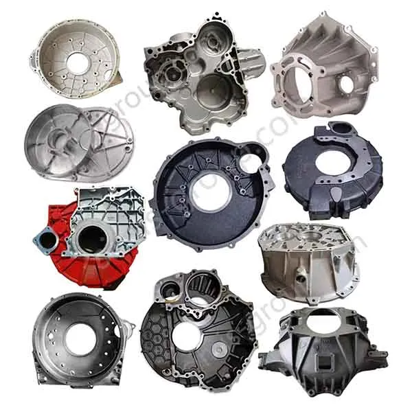
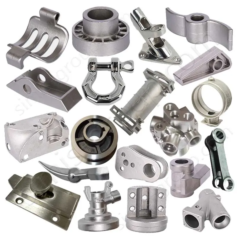
SIMIS offers custom cast and CNC-machined bearing seats and housings for industrial machinery, gear drives, pumps, motors and heavy equipment. We work from customer-supplied drawings for one-piece or split configurations, flanged supports, pedestal-style housings and special mounting geometries. Rather than assigning a single process to every design, we evaluate material, casting complexity, machining allowance and production quantity together.
Related OEM applications include gearbox housings and motor housings, where bearing-position accuracy influences the performance of the complete rotating assembly.

Choosing the Right Manufacturing Process for Bearing Seats
The bearing interface is usually a precision-machined feature, but the most economical way to make the surrounding housing depends on the size, shape, quantity and required alloy. The aim is to create a sound, stable blank with enough stock for accurate finishing of the bore, mounting faces and bolt locations.
Sand Casting for Heavy and Complex Housings
For large cast-iron bearing supports with ribs, feet, split joints or substantial wall sections, sand casting can be a practical route. During drawing review, the areas around the bearing bore, base and fastener bosses need particular attention to section transitions, moldability and machining stock. The precision bearing surfaces are finished after casting rather than relying on the as-cast size.
Shell Mold Casting for Repeatable Medium-Size Components
For compatible geometries and production volumes, shell mold casting may provide a more consistent near-net blank and reduce excess finishing work. It is considered on a project basis, especially when repeatability, part shape and tooling economics justify the process.
Aluminum Die Casting or Machining for Lightweight Designs
Some high-volume, lightweight housings can be evaluated for aluminum die casting. Bearing-bore location, local wall thickness, porosity sensitivity and subsequent machining must be considered during design review. For simpler low-volume parts, machining from solid material may be more appropriate than investing in casting tooling.
CNC Machining of Functional Surfaces
Regardless of how the blank is made, precision CNC machining establishes the specified bearing pockets, split-joint faces, locating shoulders, bolt holes and mounting datums. The machining sequence and workholding scheme should control the relationship among those features, not merely the diameter of each bore considered alone.

Material Selection for Custom Bearing Supports
Material selection should follow the actual loading and assembly requirements. A stiff base with a well-machined bore may be more important than selecting the highest-strength alloy on paper; in other cases, repeated shock or a weight limit may control the decision.
| Material option | Why it may be considered | Drawing / application review |
|---|---|---|
| Gray cast iron | Machinability, damping and rigidity | Machine frames, stationary bearing pedestals, vibration conditions |
| Ductile iron | Strength and toughness for demanding duty | Impact loads, heavy equipment and mounting bosses |
| Carbon / alloy steel | Potential fit for high-load or special fabrication requirements | Specified grade, heat treatment and weldability where relevant |
| Aluminum alloy | Low weight and useful thermal conductivity | Motor supports, expansion, stiffness and bearing-fit strategy |
For iron components, see SIMIS custom iron casting capabilities. Where a lighter housing is being evaluated, review the aluminum casting options. Final grade and any heat treatment must match the approved specification, not a generic material recommendation.

Bearing Bore Accuracy, Split Joints and Machining Datums
A precisely machined bore can still cause assembly problems if it is positioned incorrectly relative to the mounting base or a second bearing. For this reason, bearing housing drawings should clearly identify the datum system and how each critical geometric tolerance is to be evaluated.
Bore Fit and Geometry
Check the bearing outside diameter, specified housing fit, roundness or cylindricity, bore depth and shoulder geometry. A tolerance designation such as H7 may appear on some drawings, but it should not be assumed for every bearing: the required fit depends on load direction, bearing arrangement, material and temperature conditions.
Alignment and Workholding
If two bearing locations support a common shaft, their relative position and coaxiality may be just as important as individual bore diameters. A process plan can consider machining bearing bores and reference faces in controlled setups, with intermediate inspection where needed to manage distortion or accumulated error.
Split-Housing Assembly
Split bearing housings may need their mating faces, locating features, fastener pattern and assembled bore verified as a system. When the design requires finish machining with the cap installed, the drawing should make the assembly and inspection condition explicit. Oil grooves, seals, drains and lubrication passages also need to be reviewed for accessibility and cleanliness.

Inspection and Quality Requirements for OEM Bearing Housings
For custom parts, the most useful quality plan links each test to a known drawing requirement. Depending on the project, agreed checks may include:
Dimensional verification: bearing-bore diameter, base flatness, bore-to-datum position, coaxiality, bolt-hole pattern and assembled split-joint geometry.
Material verification: grade, chemistry, mechanical properties or supporting certificates where specified in the purchase documents.
Surface condition: roughness of bearing-contact and locating surfaces, burr removal, coating boundaries and protection during shipping.
Casting examination: visual inspection and, where appropriate and agreed, NDT focused on areas that matter to the design.
Traceability: part identification, measurement reports and batch records to the level required by the customer.
A CMM, bore gauge or other suitable metrology method may be selected according to feature geometry and tolerance. Not every bearing seat requires the same inspection package; the acceptance criteria must be established before production. For broader context, see the SIMIS quality control page.

Typical Applications and Design Considerations
Custom bearing seats appear throughout rotating industrial equipment, but each application creates different manufacturing priorities:
Machine tools and industrial drives: rigid support, controlled bore location and vibration behavior.
Gear reducers and transmissions: bearing-axis relationships, mounting datums and shaft alignment. See the related custom gearbox housing page.
Pumps and compressors: bearing support relative to shaft seals and coupling geometry. Explore custom pump housings.
Mining and heavy equipment: resistance to impact, structural loads, dirt and challenging maintenance conditions.
Motors and power equipment: stiffness, thermal effects, overall size and assembly repeatability.
These are common engineering considerations, not a substitute for reviewing the actual equipment drawing. For an unfamiliar or redesigned bearing arrangement, bearing selection, housing fit and shaft alignment should be confirmed by the customer's engineering team.
Request a Quote for Custom Bearing Seats and Housings
Whether you need a heavy cast-iron pedestal, a split bearing housing or a lightweight precision-machined bearing support, SIMIS can review the manufacturability of your design and discuss suitable material and process options.
For a useful RFQ, send your drawing or CAD model along with the bearing designation, material specification, critical dimensions and GD&T, required surface finish, planned quantity, service conditions and acceptance requirements. Identifying the critical bearing-contact and mounting features helps us evaluate tooling, machining sequence and inspection scope.
Have a custom bearing seat drawing? Contact SIMIS to discuss your OEM project or email info@simis-group.com with your technical requirements.